Customizable modular brush system and method thereof

a modular brush and custom design technology, applied in the field of custom design modular brush systems and methods thereof, can solve the problems of inability to readily adapt brushes used in one industry to use in another industry, inability to readily benefit from the reduced cost savings resulting from mass production, and inability to purchase brushes for a particular industry or application from limited sources, etc., to achieve efficient, quick and easy customization of each modular component, and different widths.

Active Publication Date: 2013-07-30
KEYSTONE PLASTICS
View PDF23 Cites 15 Cited by
  • Summary
  • Abstract
  • Description
  • Claims
  • Application Information

AI Technical Summary

Benefits of technology

[0009]The brush system of the present invention utilizes modular components to produce a customizable brush with ease and at a low cost. Further, the brush system of the present invention may be entirely made of plastic material(s) to allow the resulting brush to be easily recyclable. The method of the brush system of the present invention can produce brushes for infinite brush applications. Further, the method of the brush system of the present invention can produce brushes for all existing industries and applications.
[0011]The base can be of various shapes, such as tubular, prism, flat, arcuate, etc., and have various cross-sections, such as rectangular, circular, etc. Optionally, a plurality of grooves is provided on the base to receive the plurality of rails to provide increased contact surfaces between the base and the rails. The grooves may take on various forms, such as linear, curved or any other desirable configuration or pattern, and may have various cross-sectional shapes. The density and pattern of the grooves can be easily formed depending on the intended application of the resulting brush.
[0013]Each strip brush element has a coupling end and at least one brush element extending therefrom. The brush element can be in the form of bristles, tufts of bristles, baffle strip, stripping, etc. and made of metal, felt, thermoplastic, thermoset, micro fiber, or other flexible material, etc. The cross section of the coupling end has a wider profile than the brush element profile such that the strip brush element is received and secured in the channel formed between adjacent rails. The coupling end of the strip brush element can have different widths for secured receipt in the channels. A narrower or flexible coupling end provides the flexibility to conform to curved, or other patterned, channels. After sliding the strip brush element into and between the channels, a holder can be mounted onto the base or the rails to prevent the strip brush element from sliding out of the rails.
[0014]The use of thermoplastic or thermoset material in the brush system of the present invention allows efficient, quick and easy customization of each modular component at a low cost, with the resulting brush being easily recyclable, and even possibly bio-degradable. The density and pattern of the resulting brush can be customized by manipulating the width, density and pattern of the rails and strip brush elements. Different types of brushes for use in different industries and different applications can be produced with different sizes and shapes bases. There is no limitation on the size or shape of the resulting brush. There is minimal tooling cost and there is no need to use highly skilled welding professionals in connection with the brush system of the present invention. A customized brush of the present invention can easily be produced as by a mass production. Small quantities of unique brushes can be easily fabricated with simple fabrication equipments and minimally skilled laborer.

Problems solved by technology

Typically, due to the varied developments over the years of commercial brushes, brushes used in one industry cannot easily be adapted for use in another industry.
Therefore, purchaser of a brush for a particular industry or application has limited sources.
And since a manufacturer is unable to provide brushes to different industries, it cannot readily benefit from the reduced cost savings resulting from mass production.
While the core with brush elements and gutter broom are normally produced by the same manufacturer, the processes for their manufacturing are very different and require separate sets of machinery to produce.
The mixed use of a metal core with either metal or plastic bristles does not allow such brush to be easily recyclable.
There are many disadvantages and limitations to this prior art process: (1) dies used for the extrusion process is limited in size so that only certain maximum diameters can be produced; (2) extruded sections are extremely heavy since the material is thick and is impossible to reduce the mass by inserting cavities; (3) extremely expensive tooling costs, and in most cases, restricted to shapes and sizes for a particular industry or market; (4) extruded metal tends to cure and bend while cooling, requiring the need to rework for dynamic balancing for high speed usage; (5) extruded U-shape channels must align with the axial length of the core; and (6) difficult, if not impossible, to provide different patterns (such as helix, or non-linear) on the core.
There are many disadvantages and limitations to this prior art process: (1) dies used for the roll forming of the U-shape channel is limited in size so that only certain maximum diameters can be produced; (2) each U-shape channel has a maximum width before it will not make sufficient contact with the core; (3) extremely expensive tooling costs, and in most cases, restricted to shapes and sizes for a particular industry or market; (4) if non-corrosive material is needed, expensive and difficult to work with when welding; (5) requires the use of a large and expensive spot welding machine to weld the U-shape channels to the core; (6) axial length of the core is limited to the size of the spot welding machine; (7) skilled and time intensive labor required to weld the seams of the U-shape channels every few inches across the entire length of the core to prevent the U-shape channels from pulling off at the seam; (8) U-shape channels can only be mounted along the axial length of the core; and (9) difficult, if not impossible, to provide different patterns (such as helix or non-linear) on the core.
There are many disadvantages and limitations to a staple set brush: (1) the core cannot be efficiently reused since the metal staples must first be removed; (2) core must be of sufficient thickness to support the stapled bristles; (3) the use of a thick core is costly; and (4) the use of a thick core is heavy, difficult to manipulate and increases shipping costs.

Method used


Image

  • Customizable modular brush system and method thereof
  • Customizable modular brush system and method thereof
  • Customizable modular brush system and method thereof

Examples


Embodiment Construction

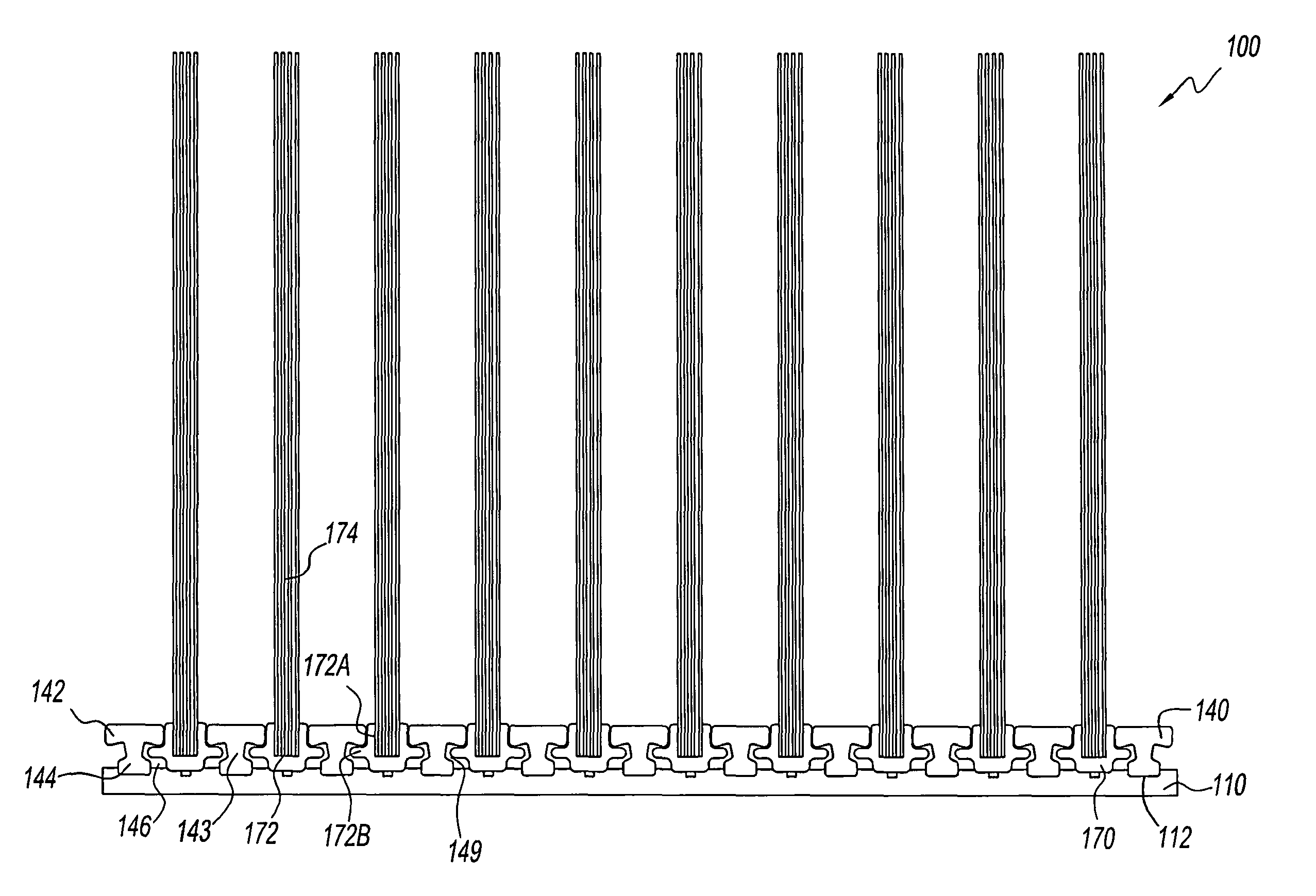
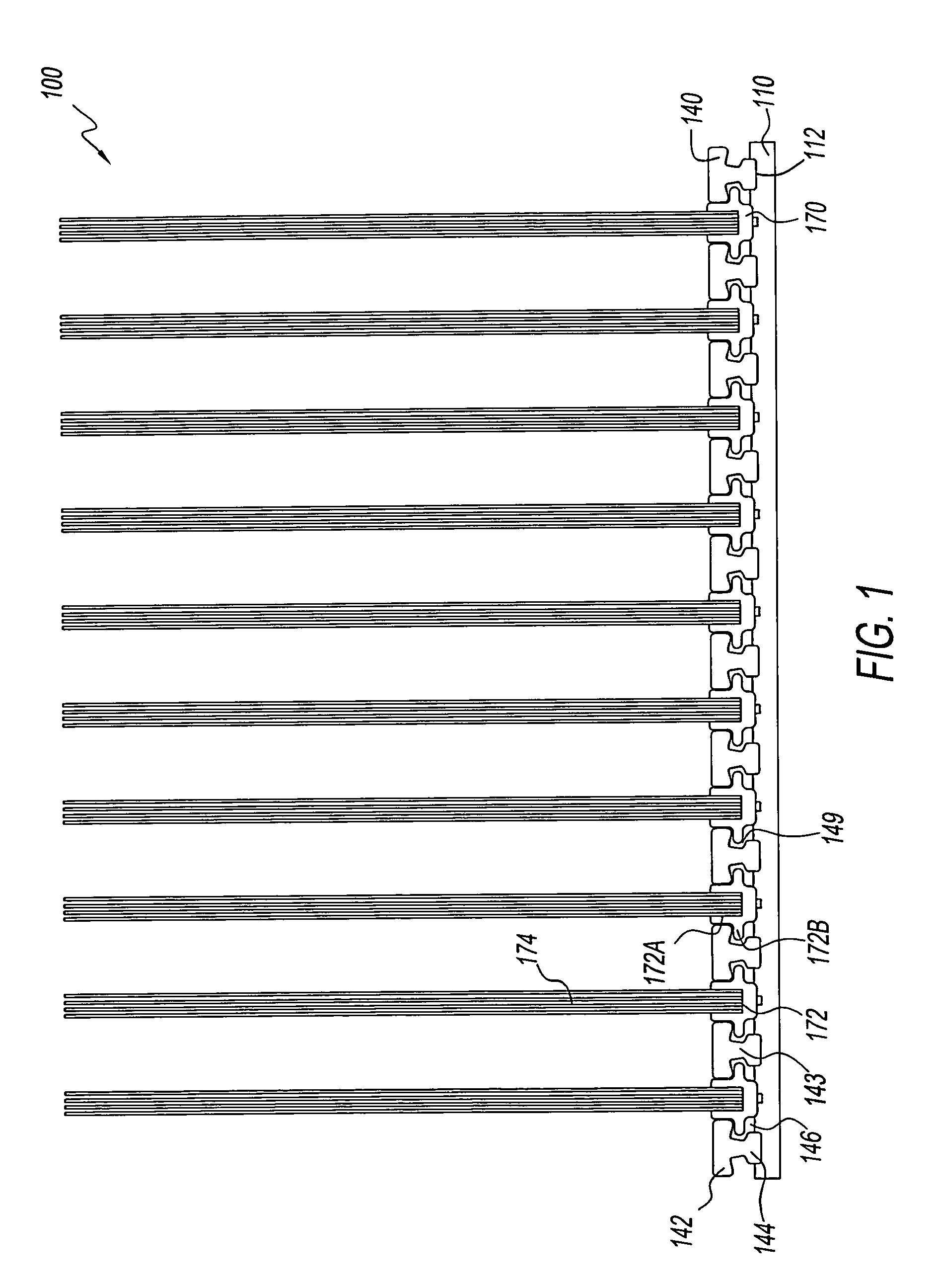
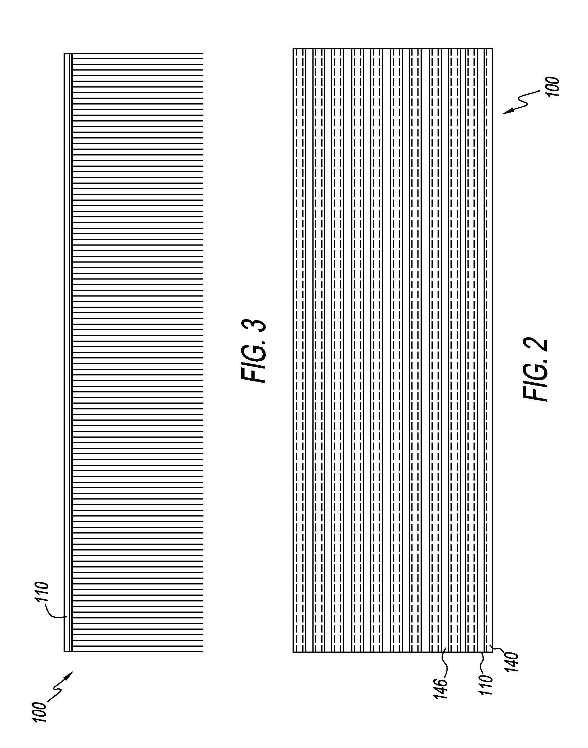
[0037]With reference to the drawings, wherein the same reference number indicates the same element throughout, there is shown in FIGS. 1-3 a brush 100 of the present invention. The brush 100 comprises a base 110, a plurality of rails 140 and a plurality of strip brush elements 170, all of which may be made of a thermoplastic or thermoset material. Each of these components, base 110, rail 140 and strip brush element 170, may be extruded, molded, or otherwise produced by methods known to one skilled in the art.

[0038]As shown in FIGS. 1-3, base 110 has a planar rectangular shape with a plurality of spaced apart and longitudinal grooves 112 on its surface. Grooves 112 are formed on the base 110 by cutting, carving, grounding, etching or milling. The density of the grooves 112 can be customized to the specific application or use. A plurality of elongated rails 140 are fastened, spaced apart and longitudinally, in the grooves 112 of the base 100 by means known to one skilled in the art, b...


PUM


Abstract

A system and method that utilizes modular components to form a customizable brush for different applications with ease and at a low cost. The system and method utilizes three main components: a base, a plurality of rails, and a plurality of strip brush elements. The plurality of rails is fastened to the base and the plurality of rails holds the strip brush elements to the base to form a brush. All three components may be made of a thermoplastic or thermoset, non-metallic material which can be either rigid or flexible to allow the resulting brush to be easily recyclable.

Description

FIELD OF THE INVENTION[0001]The invention relates to a customizable modular brush system and method thereof. In particular, a system that utilizes modular components to provide a customizable brush for different applications with ease and at a low cost.BACKGROUND OF THE INVENTION[0002]Different types of brushes are utilized in different industries and for different applications. Commercial brushes, such as those for use in connection with street sweepers, car washes, in-plant sweepers, airports, etc., are highly customized for its specific application. Typically, due to the varied developments over the years of commercial brushes, brushes used in one industry cannot easily be adapted for use in another industry. Different manufacturers use different machinery to produce the brushes. Therefore, purchaser of a brush for a particular industry or application has limited sources. And since a manufacturer is unable to provide brushes to different industries, it cannot readily benefit from...

Claims


Application Information

Patent Timeline
Patent Type & Authority Patents(United States)
IPC IPC(8): A46B7/10
CPCA46B3/00A46B5/06A46B7/00A46B7/044A46B9/02A46D3/00A46B7/04A61B1/122A46B13/005
Inventor NAFTAL, BRIAN
Owner KEYSTONE PLASTICS
Why Eureka
Try Eureka