Pressure washer device employing a cool bypass

a technology of pressure washer and bypass, which is applied in the direction of positive displacement liquid engine, combustion type, etc., can solve the problems of unfavorable system shutdown, and device has a tendency to overheat the cleaning fluid and/or develop unacceptably high system pressure, etc., to prevent siphoning and prevent overheating the pump

Active Publication Date: 2013-07-30
KARCHER FLOOR CARE +1
View PDF15 Cites 17 Cited by
  • Summary
  • Abstract
  • Description
  • Claims
  • Application Information

AI Technical Summary

Benefits of technology

[0011]It is one aspect of the present invention to provide a pressure washing system that prevents siphoning of cleaning solution into a fluid supply tank when the pressure washer device is in a bypass mode. It is a further aspect of the present invention to provide a pressure washer device with an unloader bypass valve that allows for the introduction of cooler fluid into a bypass fluid circuit to prevent overheating of the pump. These and other advantages are achieved by the device of the present invention.
[0014]The novel addition of a reduced diameter bypass conduit allows the fluid in the pressure washer device to recirculate when the trigger of the spray gun assembly is not in use, but also prevents the siphonage of cleaning solution into the fluid supply tank because a portion of the fluid is bypassed to the water supply tank. In addition, the reduced diameter bypass conduit deposits into the tank a portion of the heated and bypassed fluid. Approximately that same amount of fluid is thereafter supplied from the tank to the inlet line 14, introducing a cooler fluid from the water supply tank to the bypass fluid circuit. This introduction of cooler fluid helps to ensure that the overall temperature of the recirculated fluid will not increase and cause overheating of the pump or other device components. Thus, a thermal relief valve, commonly employed in such systems, is not required.

Problems solved by technology

In this condition, the device has a tendency to overheat the cleaning fluid and / or develop unacceptably high system pressures.
However, these systems do not always prevent overheating and often result in unwanted system shut downs.
As will be appreciated by one of skill in the art, the temperature of the re-circulating fluid will eventually rise (e.g., reach the boiling point of the fluid in about 20 minutes), which can damage the pressure washer components.
This device, however, does not generally employ a thermal relief valve.
When the spray gun 22 is actuated, the fluid being deposited thereby will have an often undesirable concentration of detergent.
However, Berfield does not address the problem of dangerously high fluid temperature caused by continuous operation of the pump.
As will be understood by skilled artisans, this design may cause pump components to overheat, causing the damage to the device or the device to unwontedly shut down.
While Rancourt does not depend on a predetermined level of excess pressure to redirect fluid through the bypass port, Rancourt wastes a substantial amount of fluid through the use of thermal relief and pressure relief valves.
The activation of the thermal relief valve and the pressure relief valve can also require additional time and thus costs to cleaning tasks due to periods of inoperability of the pressure system that occur when the valves are active.
Rancourt also requires the use of numerous additional components to achieve its safety features, increasing manufacturing costs of the overall device substantially.
Furthermore, the prior art pressure washer devices of Berfield or Rancourt do not prevent the siphoning effect alluded to above.
Specifically, when a pressure washer device is in bypass mode, i.e. the trigger of the spray gun assembly is deactivated and the pump continues to operate to move fluid through the device, the prior art pressure washer devices often experience a siphoning effect.
As one of skill in the art will appreciate, this undesirable effect wastes detergent and subjects the item being cleaned to excess detergent, solvent, etc., which may be destructive to the item.

Method used


Image

  • Pressure washer device employing a cool bypass
  • Pressure washer device employing a cool bypass
  • Pressure washer device employing a cool bypass

Examples


Embodiment Construction

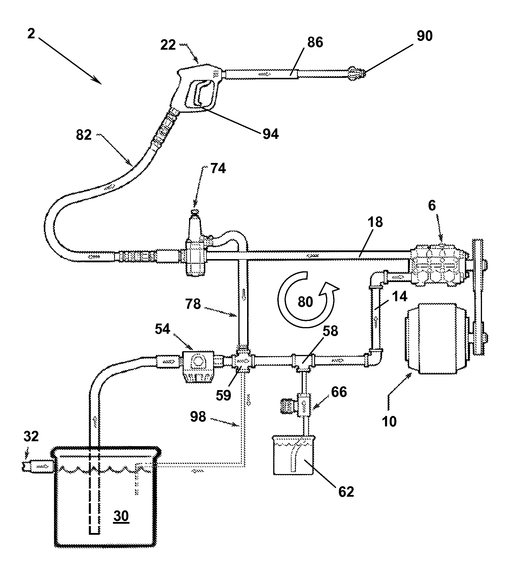
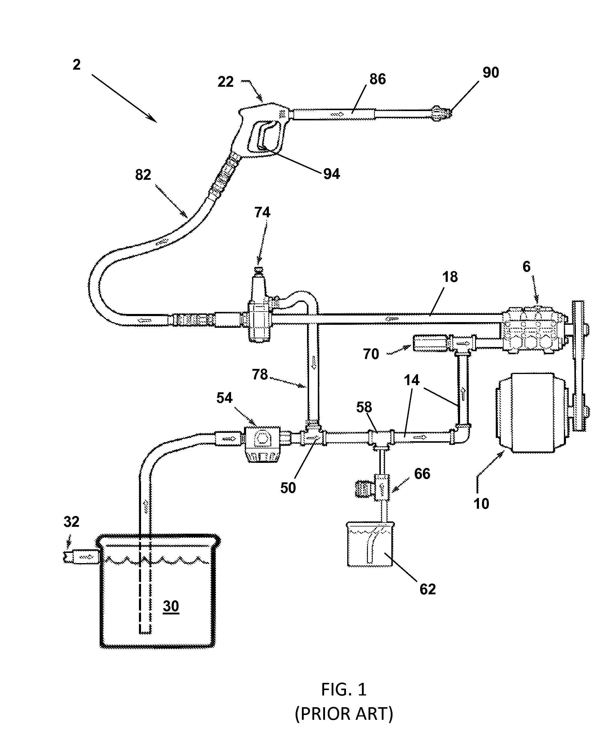
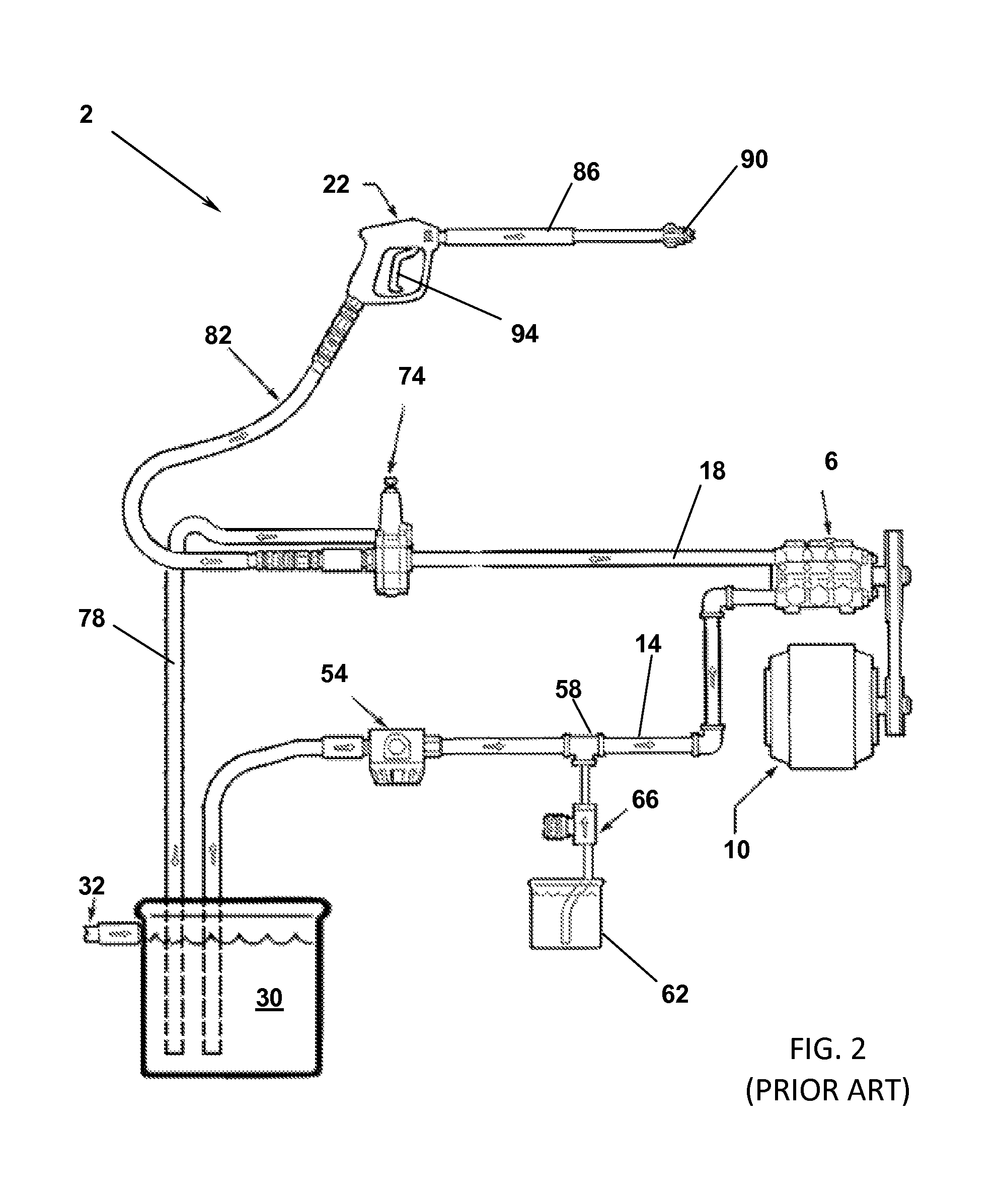
[0024]Referring now to FIG. 1, a typical pressure washer hydraulic device 2 of the prior art is shown. Here, water from a water source is directed to a fluid storage tank 30 which is interconnected via a pump inlet conduit 14 that is also associated with a tee 50. An inlet filter 54 may be positioned within the pump inlet conduit 14 to ensure that contaminants do not enter into the pressure washing device that may damage or clog the same. A second tee 58 is also associated with the pump inlet conduit 14 and is also associated with a detergent container 62 and a metering valve 66 that selectively feeds (typically via a suctioning effect) a predetermined amount of detergent to the fluid carried in the pump inlet conduit 14.

[0025]The pressure washer device system 2 also includes a pump 6 that is powered by a motor 10 by a traditional means, such as a pulley drive system. The pump 6 suctions water from the water fluid supply tank 30, which is mixed with the detergent from the detergent ...


PUM


Abstract

A pressure washer device is provided that employs an unloader bypass valve that directs a selective amount of fluid via a small diameter bypass line back to a water storage tank. The small amount of fluid allows for the pump to remain working and introduces cooler water into a bypass circuit, thereby allowing the thermal relief valve to be omitted. The diameter of the bypass line is of such a diameter to prevent siphonage of the detergent associated with the pressure washer system into the water storage tank as well.

Description

FIELD OF THE INVENTION[0001]Embodiments of the present invention are generally related to a pressure washer device having a spray gun for directing pressurized fluid to a surface to be cleaned. The system employs a bypass line for directing fluid from an unloader valve to a water supply tank when a trigger of the spray gun is not depressed. The contemplated bypass line diverts only a small portion of the water to the water supply tank, which prevents unwanted siphoning of cleaning solution from a detergent container to the water supply tank. The contemplated bypass system also introduces cooler water from the water supply tank to the system pump and related components, which prevents overheating of the pressure washer device when the spray gun is not activated.BACKGROUND OF THE INVENTION[0002]Pressure washer devices are used to provide high-pressure, heated fluid to a surface to be cleaned. Such high-pressure fluid can include heated water, or a cleaning solution comprised of a mixt...

Claims


Application Information

Patent Timeline
Patent Type & Authority Patents(United States)
IPC IPC(8): B05B9/04B05B7/30B05B9/00B05B9/01E03B7/07
CPCB08B3/026B05B15/00F04B17/06F04B23/02B05B9/0403B08B2203/0205Y10T137/85954Y10T137/86171
Inventor LINTON, PAUL W.KNIGHT, DEREK
Owner KARCHER FLOOR CARE
Why Eureka
Try Eureka