Encapsulated vacuum interrupter with grounded end cup and drive rod

a vacuum interrupter and drive rod technology, applied in the direction of air-break switches, high-tension/heavy-dress switches, electrical apparatuses, etc., can solve the problems of large switchgear devices, increased cost, and increased installation space, so as to reduce scrap costs and effective interruption

Inactive Publication Date: 2013-07-30
GLASER MICHAEL DAVID
View PDF29 Cites 31 Cited by
  • Summary
  • Abstract
  • Description
  • Claims
  • Application Information

AI Technical Summary

Benefits of technology

[0022]In another embodiment of the double break vacuum switch, the space formerly occupied by the internal cavity may be utilized to install an actuator within the encapsulation. The actuator has a flange at the bottom that allows it to be mounted onto a shoulder formed in the cavity in the encapsulation described above. In this way if issues arise during manufacture or use, the actuator may be replaced or salvaged, resulting in reduced scrap costs. When the actuator mechanism is mounted in the encapsulation, an extension rod and adapter is threaded onto the capacitive voltage divider drive rod to allow tolerance accumulation to be adjusted out, so that a slot in the adapter can be made to align with a cross hole in the portion of the plunger that extends below the drive mechanism. The extension rod and adapter also serve to place the vacuum module and actuator at ground potential. A flanged cover preferably fabricated from steel is placed over the end of the plunger that contains a contact pressure spring within and engages an external opening spring with the flanged portion. The cover has a cross-hole there through; so that it may be lined up with the slot in the adapter and the cross-hole in the plunger. A pin is placed through these three components and also through a pair of external linkages. The linkages extend down from the drive mechanism and also extend down to a chamber that contains a manual operating handle, contact position indicator, counter, electronic control board for a drive mechanism and electrolytic capacitors to energize the opening and closing coils. These items are contained in a housing attached to the lower portion of the encapsulation. The co

Problems solved by technology

The electrical current results in heating which over time will degrade the electrical insulating properties of the epoxy insulation and can result in eventual failure.
Increasing the distance from the vacuum interrupter to the actuating mechanism frame results in a large switchgear device, which is undesirable as it adds cost and requires more space for installation.
All of these devices are attempts to deal with the high voltage stresses within the internal cavity and they still result in switchgear that is unnecessarily large and

Method used


Image

  • Encapsulated vacuum interrupter with grounded end cup and drive rod
  • Encapsulated vacuum interrupter with grounded end cup and drive rod
  • Encapsulated vacuum interrupter with grounded end cup and drive rod

Examples


Embodiment Construction

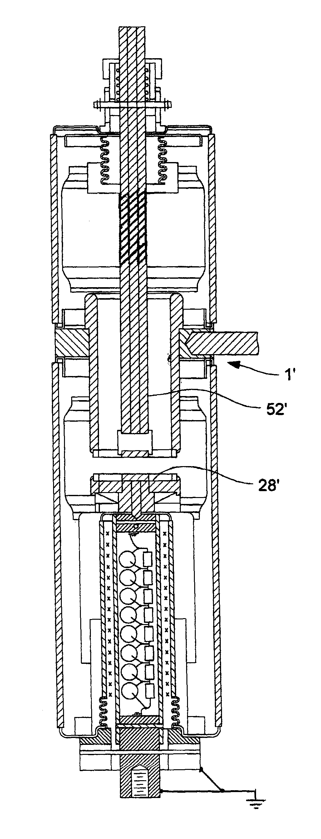
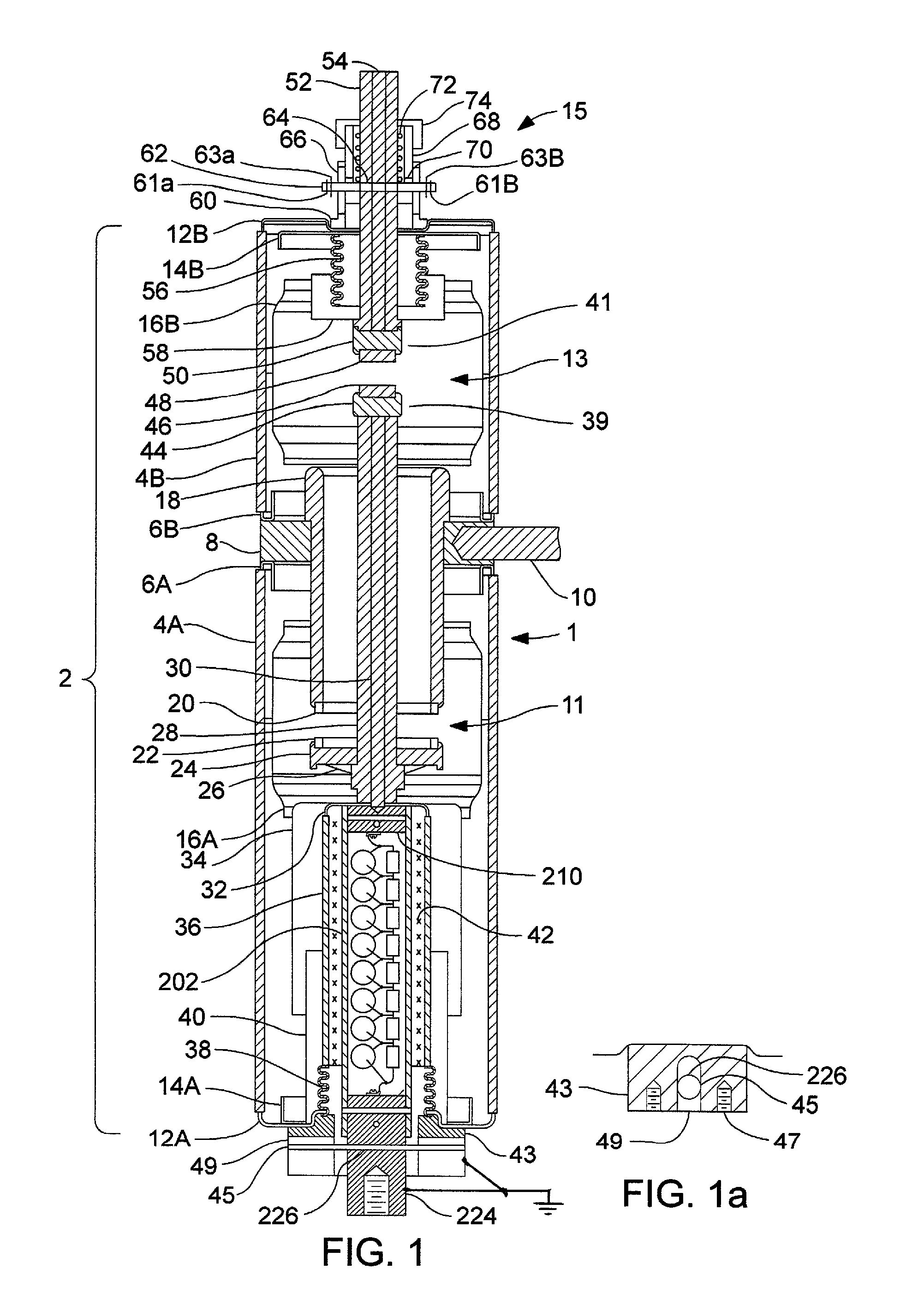
[0035]The encapsulated vacuum interrupter with grounded lower end cup and drive rod utilizes a double break vacuum switch 1 shown in FIG. 1, which comprises a vacuum envelope 2. The vacuum envelope 2 includes a pair of insulating cylinders 4A and 4B preferably made of alumina ceramic joined end-to-end by way of two triple point shields 6A and 6B preferably fabricated from stainless steel or monel and a stationary contact support ring 8 preferably fabricated from copper. A threaded hole in the stationary contact support ring 8 allows the attachment of a terminal rod 10 preferably fabricated from copper to facilitate electrical connection to the source line. The opposite ends of the ceramic cylinders are enclosed by two end cups 12A and 12B preferably fabricated from stainless steel or monel. A second set of triple point shields 14A and 14B are attached to the two end cups 12A and 12B. A generally tubular internal shield 16A and 16B preferably fabricated of stainless steel is provided...


PUM


Abstract

An encapsulated vacuum interrupter with grounded end cup and drive rod is disclosed. The double break vacuum interrupter includes a first contact system including an annular stationary contact which is engaged by a primary moving contact with the moving contact drive rod extending through the primary moving contact and through the opening of the annular stationary contact. A second contact system includes a secondary moving contact placed on the end of the moving contact rod, which engages and operates a floating contact, which moves along the same axis. A mechanical adjustment system is provided for the floating contact. A coaxial moving contact drive rod system is provided. With the encapsulated vacuum interrupter, the lower portion of the vacuum envelope is insulated from the current path, which allows for the elimination of the long internal cavity in the encapsulation as the lower end cup of the vacuum envelope may be grounded.

Description

CROSS-REFERENCES TO RELATED APPLICATIONS[0001]This is a continuation-in-part patent application taking priority from nonprovisional application Ser. No. 13 / 012,176 filed on Jan. 24, 2011 now U.S. Pat. No. 8,471,166.BACKGROUND OF THE INVENTION[0002]1. Field of the Invention[0003]The present invention relates to the field of high voltage vacuum switches and circuit interrupting devices and more particularly to an encapsulated vacuum interrupter with a grounded lower end-cup and drive rod, which allows an actuating mechanism to be mounted in close proximity to the vacuum module.[0004]2. Discussion of Prior Art[0005]Encapsulated vacuum switchgear is used to interrupt and control the flow of power through high voltage distribution circuits. As used here, the term “high voltage” refers to a voltage greater than 1000 volts. The encapsulated vacuum switchgear typically includes a vacuum interrupter encapsulated in an epoxy housing mounted to a cabinet or tank for the operating mechanism. Th...

Claims


Application Information

Patent Timeline
IPC IPC(8): H01H33/60
CPCH01H33/666H01H33/143H01H33/664H01H33/16H01H2033/6623H01H33/42H01H33/6647H01H33/24
Inventor GLASER, MICHAEL DAVID
Owner GLASER MICHAEL DAVID
Why Eureka
Try Eureka