Anti-reflective launch optics for laser to fiber coupling in a photoplethysmograpic device

a technology of anti-reflective launch and laser to fiber, applied in the field of photoplethysmography, can solve the problems of inability to place lasers in the sensor that is positioned in close proximity, direct on, and insufficient size of laser devices, so as to minimize back reflection, minimize the likelihood of adversely affecting the wavelength or intensity stability of light emitted, and maximize the effect of light availabl

Active Publication Date: 2013-07-30
KESTREL LABS
View PDF16 Cites 0 Cited by
  • Summary
  • Abstract
  • Description
  • Claims
  • Application Information

AI Technical Summary

Benefits of technology

[0019]In accordance with one embodiment a light launching apparatus for a photoplethysmographic device comprises a laser-based emitter coupled to a light guide wherein the coupled end of the light guide is coated to minimize back reflection. Accordingly, several advantages of one or more aspects are as follows: that the light exiting the laser does not sufficiently reflect off the light guide and become incident on the laser and thus minimizes the likelihood of adversely affecting the wavelength or intensity stability of the light emitted by the laser; that a percentage of the light emitted by the laser and incident on the light guide is lost to back reflection, thus maximizing the light available for sensing of the desired blood analytes, hemodynamic parameters, or tissue properties.

Problems solved by technology

The use of one or more lasers in photoplethysmography creates some unique challenges.
When using one or more lasers as light sources, or emitters, in a photoplethysmographic device, the lasers often cannot be placed in the sensor that is positioned in close proximity to, or directly on, the tissue-under-test, as has been typical with LED based photoplethysmographic sensors.
This might be due to the physical size of the laser device being too large for placement in a small sensor designed for application to commonly-used sensing sites such as a finger.
It also might be due to the need to position the laser in close proximity to its driver electronics, to one or more heat sinks, or to other electro-mechanical devices that, as a whole, create a package that is too large or cumbersome to place in the sensor or to conveniently position in immediate proximity to the tissue-under-test.
None of these light guide-based devices, however, addressed the problems associated with the instabilities caused by a portion of the light incident on the light guide reflecting back toward the emitter, and in specific, a laser-based emitter.
Back reflections of this magnitude can cause several adverse effects, any one of which can be detrimental to the accuracy of a photoplethysmographic measurement technology that is using laser light sources.
These detrimental effects occur because the light reflected off the surface of the light guide can re-enter the laser cavity and interfere with the performance of the laser.
Depending on the exact type of laser used, light emitted by the laser and reflected off the front surface of the light guide back toward the laser cavity can cause problems such as reducing the mode hop spacing as a function of temperature, inducing additional mode hops because of secondary and tertiary resonant cavities formed between the laser facets and the light guide end face, and increasing the magnitude of the wavelength shift associated with any individual mode hop.
In laser-based photoplethysmographic instrument systems, the back reflection of light towards a source laser when launching its light into a light guide causes fluctuations in intensity and spectral content (or wavelength) that are large enough to dramatically reduce the accuracy of the photoplethysmographic measurements.
Similarly, wavelength shifts of only one nanometer can induce errors in the measurement of certain blood analytes which are large enough to make these blood analyte measurements clinically useless.
This use of anti-reflective coatings does nothing to prevent light that is being emitted by a laser and launched into a light guide from reflecting backward toward the laser and inducing the exact problems described earlier.
This application of anti-reflective coatings once again does nothing to prevent light emitted by a laser, and being launched into a light guide, from reflecting back toward the laser and causing the problems described earlier.

Method used


Image

  • Anti-reflective launch optics for laser to fiber coupling in a photoplethysmograpic device
  • Anti-reflective launch optics for laser to fiber coupling in a photoplethysmograpic device

Examples


Embodiment Construction

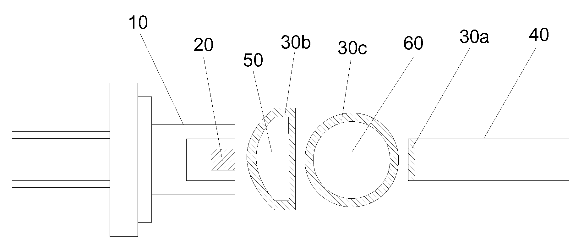
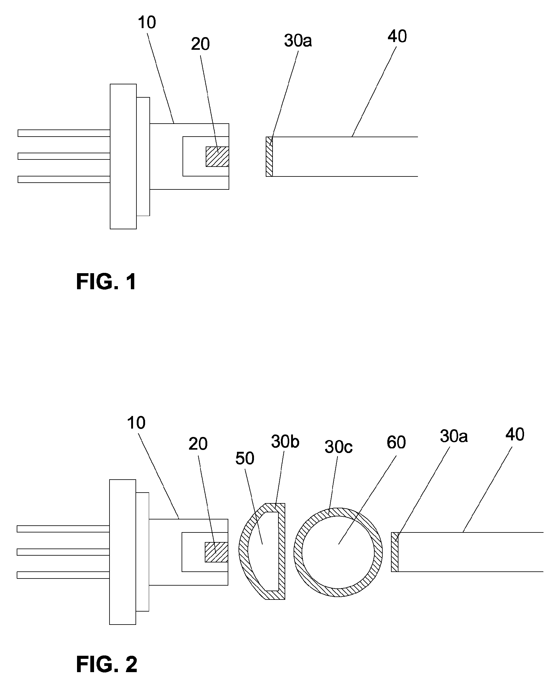
[0022]One embodiment of a light launching portion of a photoplethysmographic device is shown in FIG. 1. An emitter housing 10 contains a light source, also called an emitter. The emitter is a laser 20 but it can be any one of a number different types of lasers. The emitter shown in this figure, by way of example only, is a diode laser. A few of the possible laser types include gas lasers, diode lasers, dye lasers, or vertical cavity surface emitting lasers (VCSEL), to name a few.

[0023]The light emitted by the laser 20 is directly coupled, or launched, into a light guide 40. That is, the light emitted by the laser 20 is directly incident on and injected-into the light guide 40. The light guide 40 can accept light that is incident on its entrance face, however there may be limits to the incidence angle on the entrance face at which light can propagate into the light guide. The limits to this angle of incidence may be quantified in part by the numerical aperture of the light guide. The...


PUM


Abstract

An embodiment of a light launching portion of a photoplethysmographic device having a laser (20) light source and a light guide (40). The coupled end of the light guide (40) includes an anti-reflection coating (30a) to prevent or minimize the back reflection of light emitted by the laser (20). This minimizes the extent to which back reflected light can re-enter the laser and adversely alter the optical output properties of the laser (20) and additionally minimizes the associated light loss thus helping to maximize the optical coupling efficiency. Other embodiments are described and shown.

Description

STATEMENT REGARDING FEDERALLY SPONSORED RESEARCH OR DEVELOPMENT[0001]This invention was made with government support under R44HL073518 awarded by the National Institutes of Health. The government has certain rights in the invention.BACKGROUND-PRIOR ART[0002]U.S. PatentsPat. No.Kind CodeIssue DatePatentee7,313,427B2Dec. 25, 2007Benni7,047,054B2May 16, 2006Benni6,184,521B1Feb. 6, 2001CoffinBACKGROUND OF THE INVENTION[0003]In the science of photoplethysmography, light is used to illuminate or trans-illuminate living tissue for the purpose of providing noninvasive measurements of blood analytes or other hemodynamic parameters or tissue properties. In this monitoring modality light is directed into living tissue and a portion of the light which is not absorbed by the tissues, or scattered in some other direction, is detected a short distance from the point at which the light entered the tissue. The detected light is converted into electronic signals that are indicative of the received li...

Claims


Application Information

Patent Timeline
Patent Type & Authority Patents(United States)
IPC IPC(8): G02B6/26G02B6/42A61B5/1455
CPCA61B5/02427G02B6/4207A61B5/14552
Inventor POLOGE, JONAS ALEXANDERDELIANIDES, THEODORE PHILIP
Owner KESTREL LABS
Why Eureka
Try Eureka