
Asymmetric dual directional steerable catheter sheath

a catheter and asymmetric technology, applied in the field of intravascular catheter introduction and positioning, can solve the problems of affecting the normal activation of the left and right arteries, so as to achieve the effect of increasing ease and decreasing distan

Active Publication Date: 2013-08-06
BOSTON SCI SCIMED INC
View PDF21 Cites 106 Cited by
  • Summary
  • Abstract
  • Description
  • Claims
  • Application Information

AI Technical Summary

Benefits of technology

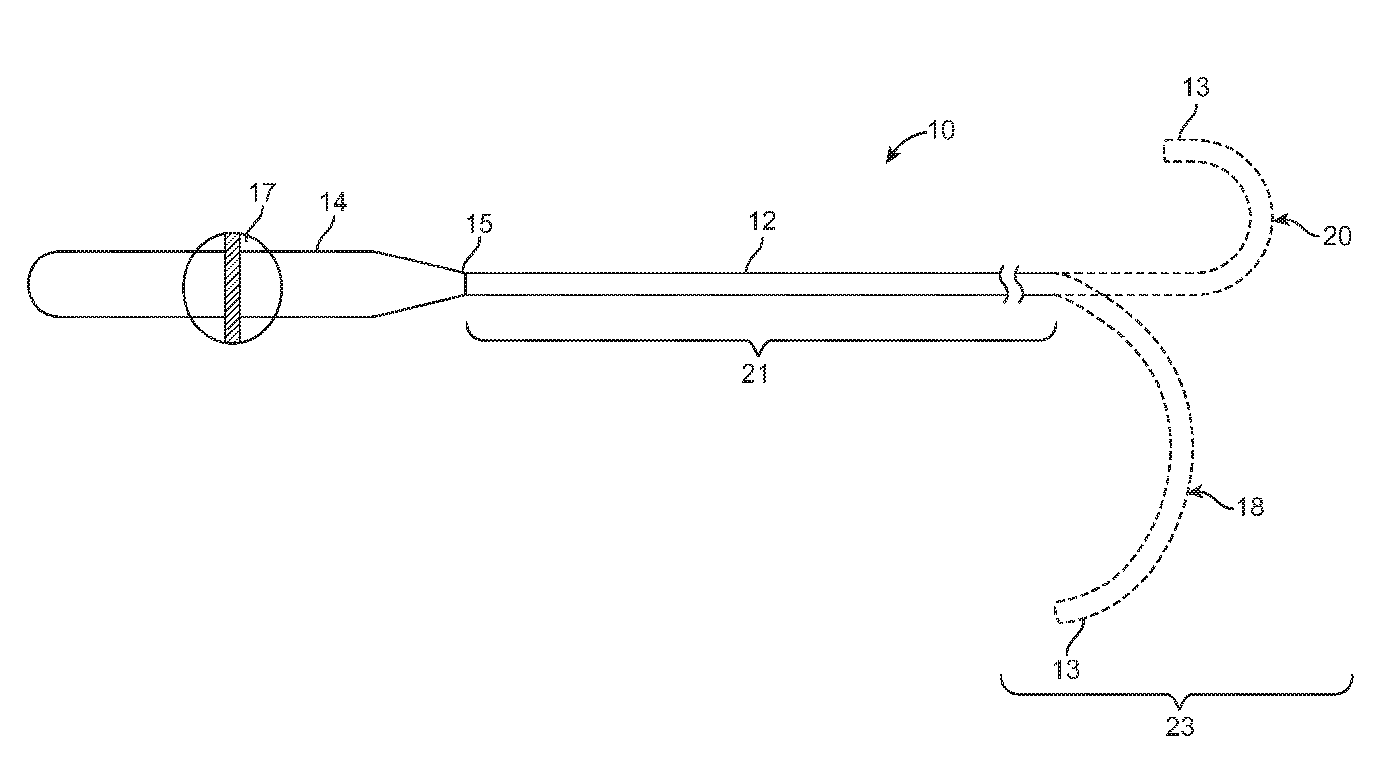
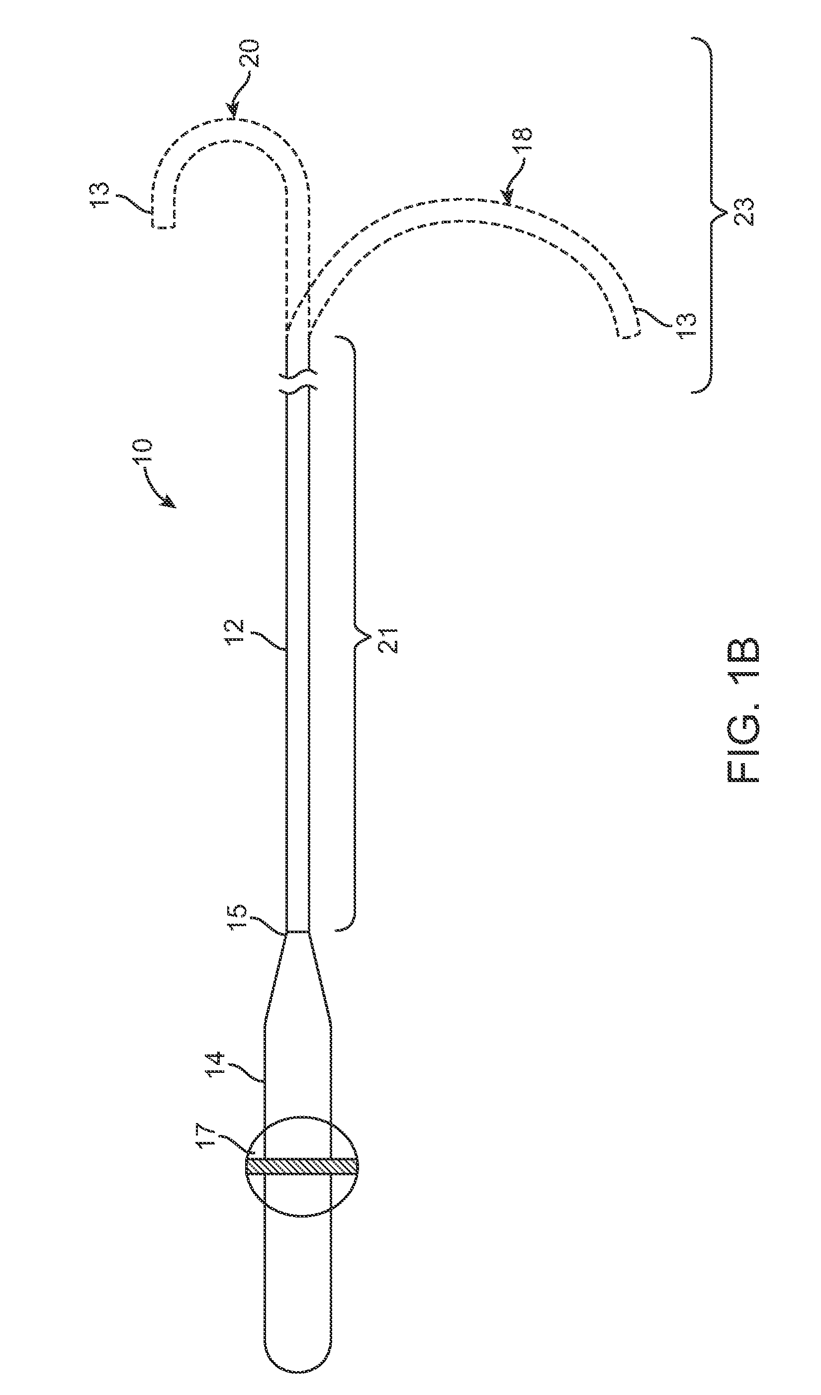
[0024]Although the disclosed inventions should not be so limited in their broadest aspects, the use of a steerable catheter sheath in the manner described above allows a user to position the catheter sheath near a target ablation site before the catheter is deployed from the sheath, thereby decreasing the distance traveled by the catheter between the distal end of the sheath and the target tissue site and increasing the ease with which the catheter is retracted back into the sheath after the ablation procedure.

Problems solved by technology

These wavelets, called “reentry circuits,” disrupt the normally uniform activation of the left and right atria.
Because of a loss of atrioventricular synchrony, people who suffer from atrial fibrillation and flutter also suffer the consequences of impaired hemodynamics and loss of cardiac efficiency.
They are also at greater risk of stroke and other thromboembolic complications because of loss of effective contraction and atrial stasis.
However, not only is the maze procedure technically difficult to do, it also requires open heart surgery and is very expensive.
While steerable guide sheaths can be used to facilitate the introduction of the catheter within the desired pulmonary vein, the simple curves provided by such steerable guide sheaths do not easily allow the guidance of the catheter within both the left and right pulmonary veins.

Method used


Image

  • Asymmetric dual directional steerable catheter sheath
  • Asymmetric dual directional steerable catheter sheath
  • Asymmetric dual directional steerable catheter sheath

Examples


Embodiment Construction

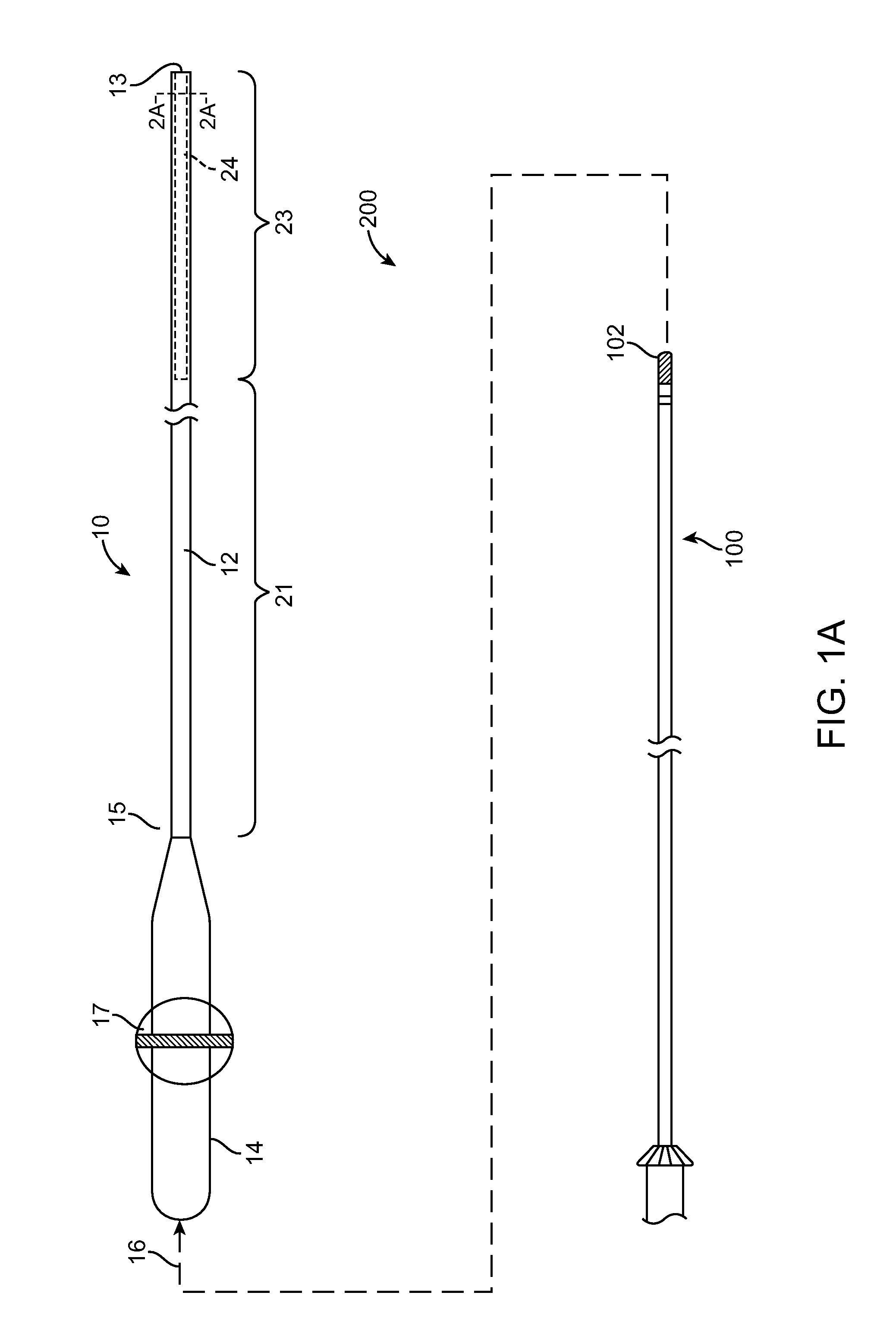
[0038]Referring to FIGS. 1A, 1A, 2A, and 2B, an exemplary assembly 200 constructed in accordance with the disclosed inventions is shown. The assembly 200 includes a catheter 100 and a steerable catheter sheath 10 sized for receiving the catheter 100 therein. In the illustrated embodiment, the catheter 100 is an ablation catheter or a mapping / ablation catheter and carries ablation and / or mapping elements on a distal end 102 thereof. The assembly 200 may further include a guide wire and / or other therapeutic tools (not shown) to be delivered into the left atrium in a desired position.

[0039]Although the steerable catheter sheath 10 is described hereinafter for use in the heart for facilitating introduction of the catheter 100 into desirable positions for mapping and ablating arrhythmia substrates, the sheath 10 may be used within any body lumens, chambers or cavities of a patient for therapeutic and diagnostic purposes in those instances where access to interior bodily regions is obtain...


PUM


Abstract

A steerable catheter sheath for use in directing a catheter into a desired position is provided. The sheath includes an elongated member configured to receive the catheter therein. The distal end of the elongated member is steerable in two directions, each direction having a different bent configuration, e.g., a sharp curve in one direction and an open arching curve in the other direction. A resilient structure having different bending properties in each of its lateral sides is carried in the distal portion of the elongated member and causes the asymmetric bending. In one embodiment, the resilient structure includes a hypotube with a plurality of notches and slits in the sides. In another embodiment, the resilient structure is covered in an outer coating having different durometer portions. The sheath is particularly useful for accessing left and right pulmonary veins when a transeptal entry approach is used into the left atrium.

Description

RELATED APPLICATION DATA[0001]The present application claims the benefit under 35 U.S.C. §119 to U.S. provisional patent application Ser. No. 61 / 154,244, filed Feb. 20, 2009. The foregoing application is hereby incorporated by reference into the present application in its entirety.FIELD OF THE INVENTION[0002]The disclosed inventions generally relate to systems and methods for introducing a medical probe adjacent to target tissue, and more particularly to a steerable sheath for intravascularly introducing and positioning a catheter into a body cavity, such as a heart chamber.BACKGROUND OF THE INVENTION[0003]Normal sinus rhythm of the heart begins with the sinoatrial node (or “SA node”) generating an electrical impulse. The impulse usually propagates uniformly across the right and left atria and the atrial septum to the atrioventricular node (or “AV node”). This propagation causes the atria to contract in an organized manner to transport blood from the atria to the ventricles, and to ...

Claims


Application Information

Patent Timeline
Patent Type & Authority Patents(United States)
IPC IPC(8): A61B18/14
CPCA61B18/1492A61M25/0138A61M25/0141A61M25/0147A61B2017/00243A61B2017/003A61M2025/0161
Inventor WATSON, JAMES R.
Owner BOSTON SCI SCIMED INC
Learn More