Smooth SiConi etch for silicon-containing films

a silicon-containing film and smooth siconi technology, applied in decorative arts, electrical equipment, electrical discharge tubes, etc., can solve the problems of difficult to realize the effect of etching silicon, difficult to achieve etching, and difficulty in reducing the size of solid by-products, so as to reduce the roughness of the post-etch surface and reduce the difference in etching rate. , the effect of reducing the flow ratio of hydrogen

Active Publication Date: 2013-08-06
APPLIED MATERIALS INC
View PDF13 Cites 212 Cited by
  • Summary
  • Abstract
  • Description
  • Claims
  • Application Information

AI Technical Summary

Benefits of technology

[0006]A method of etching silicon-containing material is described and includes a SiConi™ etch having a greater or lesser flow ratio of hydrogen compared to fluorine than that found in the prior art. Modifying the flow rate ratios in this way has been found to reduce roughness of the post-etch surface and to reduce the difference in etch-rate between densely and sparsely patterned areas. Alternative means of reducing post-etch surface roughness include pulsing the flows of the precursors and / or the plasma power, maintaining a relatively high substrate temperature and performing the SiConi™ in multiple steps. Each of these approaches, either alone or in combination, serve to reduce the roughness of the etched surface by limiting solid residue grain size.
[0007]In one embodiment, a method of etching a silicon-containing layer on a surface of a substrate in a substrate processing region of a substrate processing chamber, which leaves a relatively smooth post-etch surface, includes flowing a fluorine-containing precursor and a hydrogen-containing precursor into a first remote plasma region fluidly coupled to the substrate processing region while forming a plasma in the first plasma region to produce plasma effluents. The flow rate of the fluorine-containing precursor and the flow rate of the hydrogen-containing precursor result in a hydrogen-to-fluorine atomic flow ratio of less than 1:1 or greater than 5:1. The method further includes etching the silicon-containing layer by flowing the plasma effluents into the substrate processing region while forming solid by-products on the surface of the substrate, and sublimating the solid by-products to leave the relatively smooth post-etch surface by increasing a temperature of the substrate above a sublimation temperature of the solid by-products.
[0008]In yet another embodiment, a method of etching a silicon-containing layer on a surface of a substrate in a substrate processing region of a substrate processing chamber, which reduces a difference in etch-rate between a densely patterned area and a sparsely patterned area, includes flowing a fluorine-containing precursor and a hydrogen-containing precursor into a first remote plasma region fluidly coupled to the substrate processing region while forming a plasma in the first plasma region to produce plasma effluents. The flow rate of the fluorine-containing precursor and The flow rate of the hydrogen-containing precursor result in a hydrogen-to-fluorine atomic flow ratio of less than 1:1 or greater than 5:1. The method further includes etching the silicon-containing layer in the densely patterned area and the sparsely patterned area by flowing the plasma effluents into the substrate processing region while forming solid by-products on the surface of the substrate, and sublimating the solid by-products by increasing a temperature of the substrate above a sublimation temperature of the solid by-products.

Problems solved by technology

The SiConi™ etch is largely conformal and selective towards silicon oxide layers but does not readily etch silicon regardless of whether the silicon is amorphous, crystalline or polycrystalline.
However, as technology shrinks to 32 nm trench widths and beyond, the dimensions of these solid by-products become non-negligible compared with the smallest dimension of the trench.
The appreciable size of the solid by-products may pose challenges relating to ILD recess surface roughness and trench-to-trench variability of the height of the silicon oxide interface.

Method used


Image

  • Smooth SiConi etch for silicon-containing films
  • Smooth SiConi etch for silicon-containing films
  • Smooth SiConi etch for silicon-containing films

Examples


Embodiment Construction

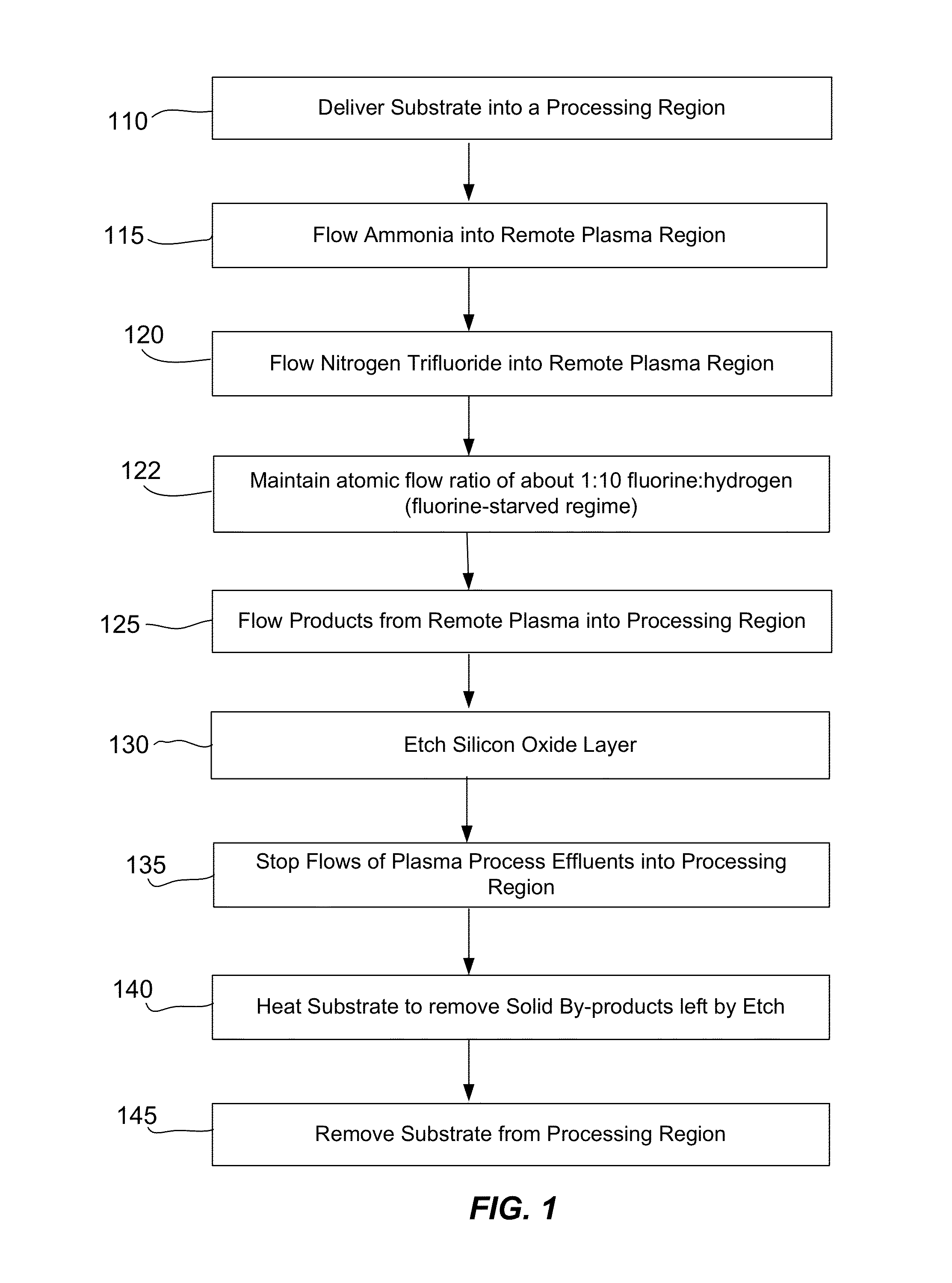
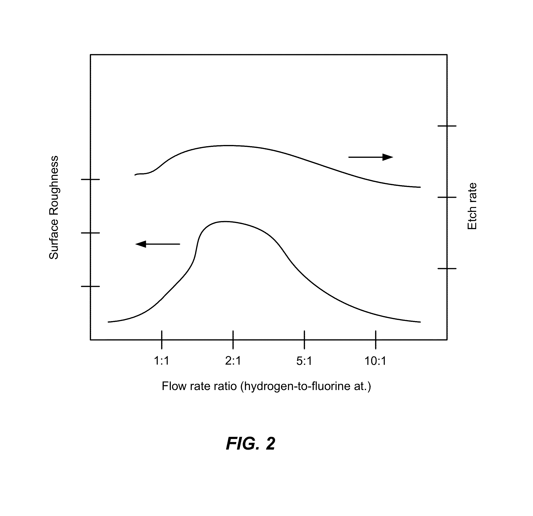
[0021]A method of etching silicon-containing material is described and includes a SiConi™ etch having a greater or lesser flow ratio of hydrogen compared to fluorine than that found in the prior art. Modifying the flow rate ratios in this way has been found to reduce roughness of the post-etch surface and to reduce the difference in etch-rate between densely and sparsely patterned areas. Alternative means of reducing post-etch surface roughness include pulsing the flows of the precursors and / or the plasma power, maintaining a relatively high substrate temperature and performing the SiConi™ in multiple steps. Each of these approaches, either alone or in combination, serve to reduce the roughness of the etched surface by limiting solid residue grain size.

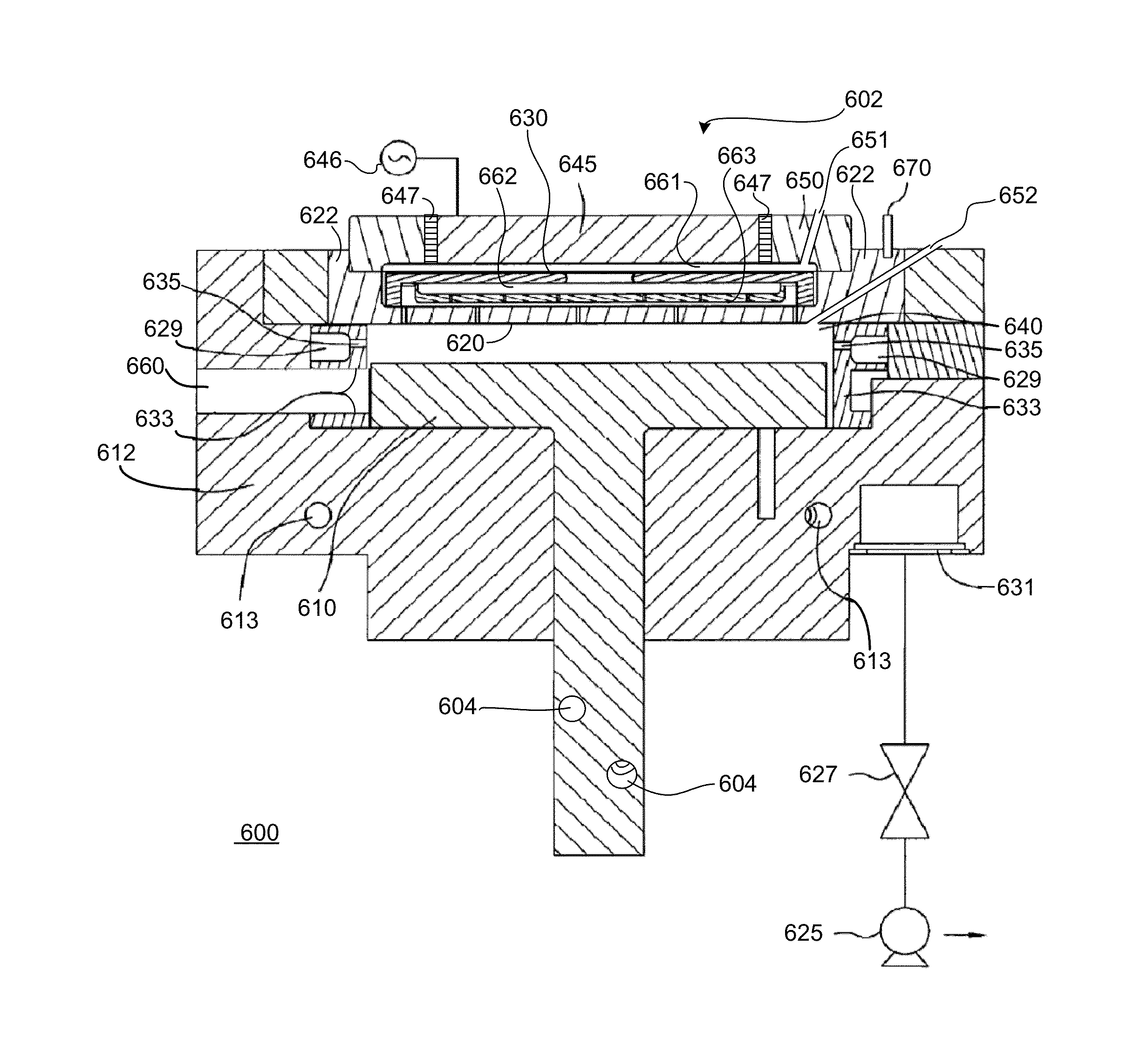
[0022]SiConi™ etch processes have used a hydrogen source of ammonia (NH3) and a fluorine source of nitrogen trifluoride (NF3) which together flow through a remote plasma system (RPS) and into a reaction region. In the past, SiConi™ et...


PUM

PropertyMeasurementUnit
repetition frequencyaaaaaaaaaa
trench widthsaaaaaaaaaa

Abstract

A method of etching silicon-containing material is described and includes a SiConi™ etch having a greater or lesser flow ratio of hydrogen compared to fluorine than that found in the prior art. Modifying the flow rate ratios in this way has been found to reduce roughness of the post-etch surface and to reduce the difference in etch-rate between densely and sparsely patterned areas. Alternative means of reducing post-etch surface roughness include pulsing the flows of the precursors and / or the plasma power, maintaining a relatively high substrate temperature and performing the SiConi™ in multiple steps. Each of these approaches, either alone or in combination, serve to reduce the roughness of the etched surface by limiting solid residue grain size.

Description

FIELD OF THE INVENTION[0001]This application relates to manufacturing technology solutions involving equipment, processes, and materials used in the deposition, patterning, and treatment of thin-films and coatings, with representative examples including (but not limited to) applications involving: semiconductor and dielectric materials and devices, silicon-based wafers and flat panel displays (such as TFTs).BACKGROUND OF THE INVENTION[0002]Integrated circuits are made possible by processes which produce intricately patterned material layers on substrate surfaces. Producing patterned material on a substrate requires controlled methods for removal of exposed material. Chemical etching is used for a variety of purposes including transferring a pattern in photoresist into underlying layers, thinning layers or thinning lateral dimensions of features already present on the surface. Often it is desirable to have an etch process which etches one material faster than another helping e.g. a p...

Claims


Application Information

Patent Timeline
Patent Type & Authority Patents(United States)
IPC IPC(8): H01L21/302
CPCH01J37/32357H01L21/31116H01J2237/3341H01L21/3065
Inventor TANG, JINGINGLE, NITINYANG, DONGQING
Owner APPLIED MATERIALS INC
Why Eureka
Try Eureka