Wireless magnetic resonance imaging apparatus generating synchronized clock-regenerated signals and video
a technology of magnetic resonance imaging and clock signal, which is applied in the direction of magnetic measurement, instruments, measurement devices, etc., can solve the problems of not disclosing a method of regenerating clock signal or transmitting clock signal by radio
- Summary
- Abstract
- Description
- Claims
- Application Information
AI Technical Summary
Benefits of technology
Problems solved by technology
Method used
Image
Examples
first embodiment
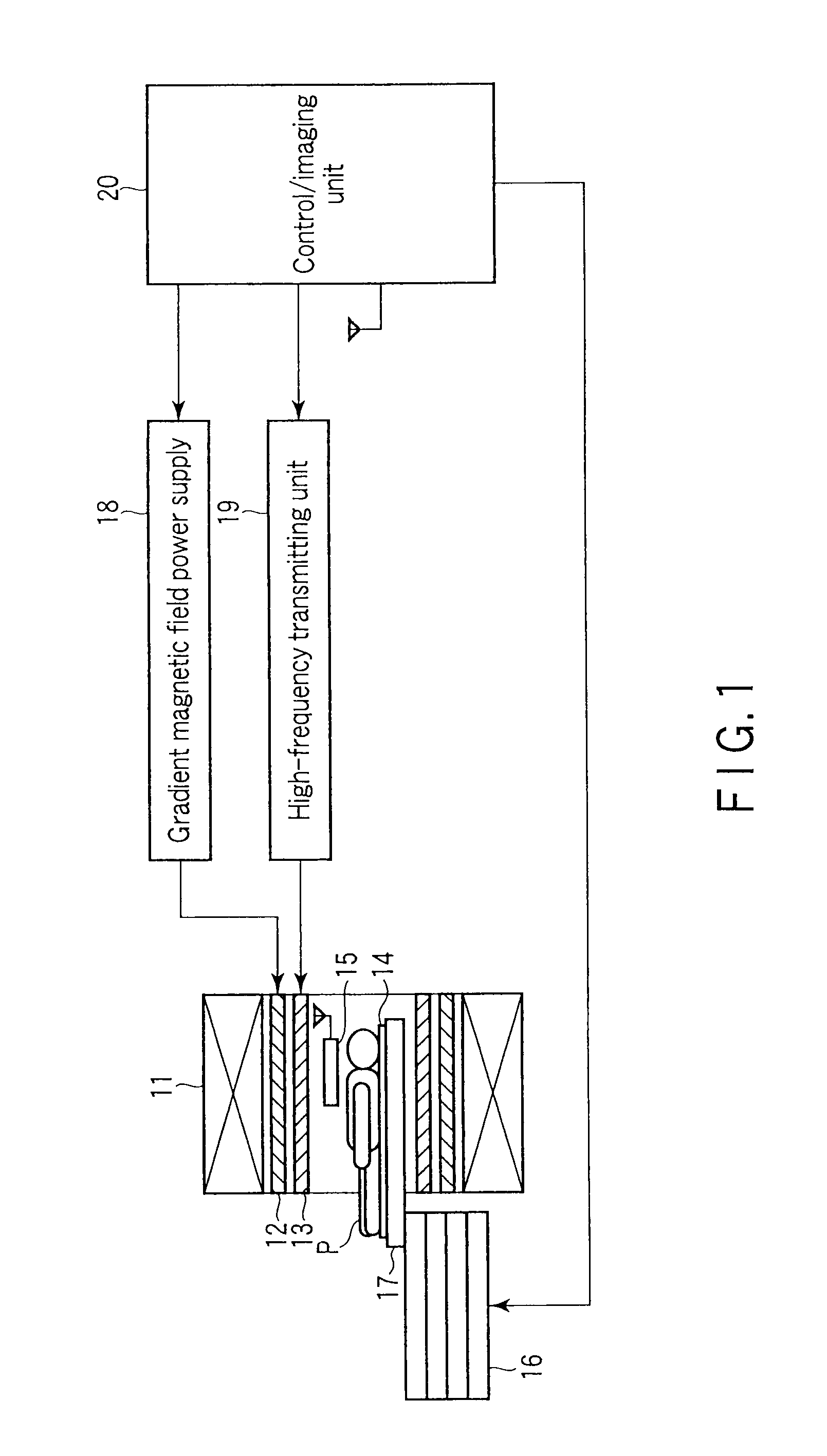
[0037]FIG. 1 shows an MRI apparatus according to a first embodiment. A magnetostatic field magnet 11, a gradient coil 12, an RF coil unit 13, a probe unit 14, a probe unit 15, and a top panel 17 included in a bed 16 are contained in a so-called gantry. The bed 16 is movable, and its position is controlled by a bed position controller described later. A gradient magnetic field power supply 18 is connected to the gradient coil 12, and a high-frequency transmitting unit 19 is connected to the RF coil unit 13. The probe unit 14 is connected to a control / imaging unit 20 via a wired channel (not shown). The other probe unit 15 is connected to the control / imaging unit 20 via a wireless channel.
[0038]The magnetostatic field magnet 11 is a hollow cylindrical member and is configured to generate a uniform magnetostatic field. A permanent magnet, superconductive magnet or the like is used as the magnetostatic field magnet 11. The gradient coil 12 is a hollow cylindrical member and is formed of...
second embodiment
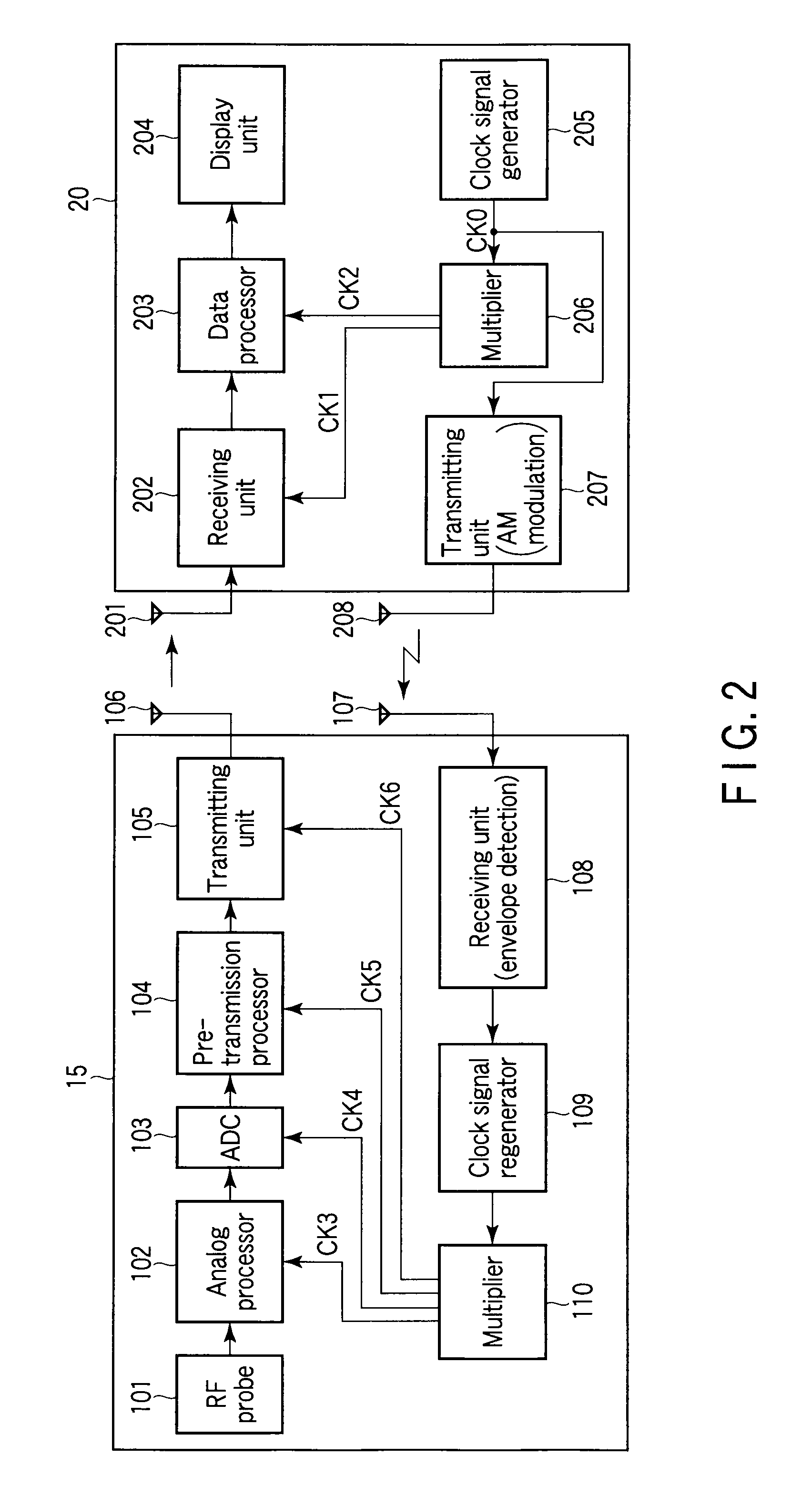
[0103]A description will now be given of a second embodiment. The MRI apparatus of the second embodiment has substantially the same configuration as the first embodiment shown in FIG. 1. FIG. 14 shows a wireless probe unit 15 and control / imaging unit 20 employed in the second embodiment.
[0104]In FIG. 14, elements similar to those of the first embodiment are denoted by corresponding reference numbers, and only different elements will be described. In the second embodiment, the clock signal generator 205 and the first type multiplier 206 are replaced with a variable phase clock generator 210, and a bed position controller 301 and a phase calculator 302 are provided in the probe unit 15. The second embodiment can prevent phase shifting during acquisition of a magnetic resonance signal, using a clock signal phase compensation function that will be described later.
[0105]The receiving antenna 107 of the probe unit 15 is located on a bed 16 controlled by the bed position controller 301. Th...
PUM
 Abstract
Description
Claims
Application Information
 - R&D
- Intellectual Property
- Life Sciences
- Materials
- Tech Scout
- Unparalleled Data Quality
- Higher Quality Content
- 60% Fewer Hallucinations
Browse by: Latest US Patents, China's latest patents, Technical Efficacy Thesaurus, Application Domain, Technology Topic, Popular Technical Reports.
© 2025 PatSnap. All rights reserved.Legal|Privacy policy|Modern Slavery Act Transparency Statement|Sitemap|About US| Contact US: help@patsnap.com


