Vehicle glazing having a trim mounted thereon

a technology for vehicle glazing and trim, which is applied in the direction of vehicle bodies, monocoque constructions, building components, etc., to achieve the effect of high pull-off for

Active Publication Date: 2013-08-13
PILKINGTON ITALA
View PDF135 Cites 14 Cited by
  • Summary
  • Abstract
  • Description
  • Claims
  • Application Information

AI Technical Summary

Benefits of technology

[0011]This engagement technique facilitates attachment of the trim, and provides significantly more secure retention of the trim. Preferably the glazing profile is moulded in situ directly on the pane. Advantageously, the insert is also moulded in situ on the pane, and the glazing profile and the insert are moulded in the same operation. This yields a more efficient manufacturing operation.
[0012]Preferably the insert comprises a strip-like main body, which is provided with at least one elongate strengthening member extending along the length of the strip-like main body. Alternatively or additionally, the strip-like main body may have at least one transverse strengthening member extending across its width. In addition to providing an improved retention mechanism, the insert may also contribute significantly to the stiffness of the glazing profile. This further assists retention of the trim, since the trim is less likely to become detached if the glazing profile which bears it is less susceptible to flexing.
[0013]Preferably the strip-like main body comprises at least one projecting member provided on the lower side of the strip-like main body to secure the insert in the glazing profile. This helps ensure that the insert is securely anchored in the glazing profile.
[0015]Preferably, the trim-retaining insert comprises a plastics material and a filler material. More preferably, the plastics material is polypropylene, and the filler material is a glass fibre filler material. An appropriate choice of filler material confers improved physical properties on the insert, for example increased stiffness, hardness and durability.

Problems solved by technology

One difficulty with bonding or clipping a trim to the edge of a glazing is ensuring that the trim and its fixing means are able to resist sufficient pull force for the trim to remain adhered to the glazing at all times in normal use.
This is a particular problem for bonding with certain types of adhesive, or in the above example where a trim is clipped to a glazing profile, which relies on the clipping force together with friction and / or a mechanical interference fit to maintain the trim in place.

Method used


Image

  • Vehicle glazing having a trim mounted thereon
  • Vehicle glazing having a trim mounted thereon
  • Vehicle glazing having a trim mounted thereon

Examples


Embodiment Construction

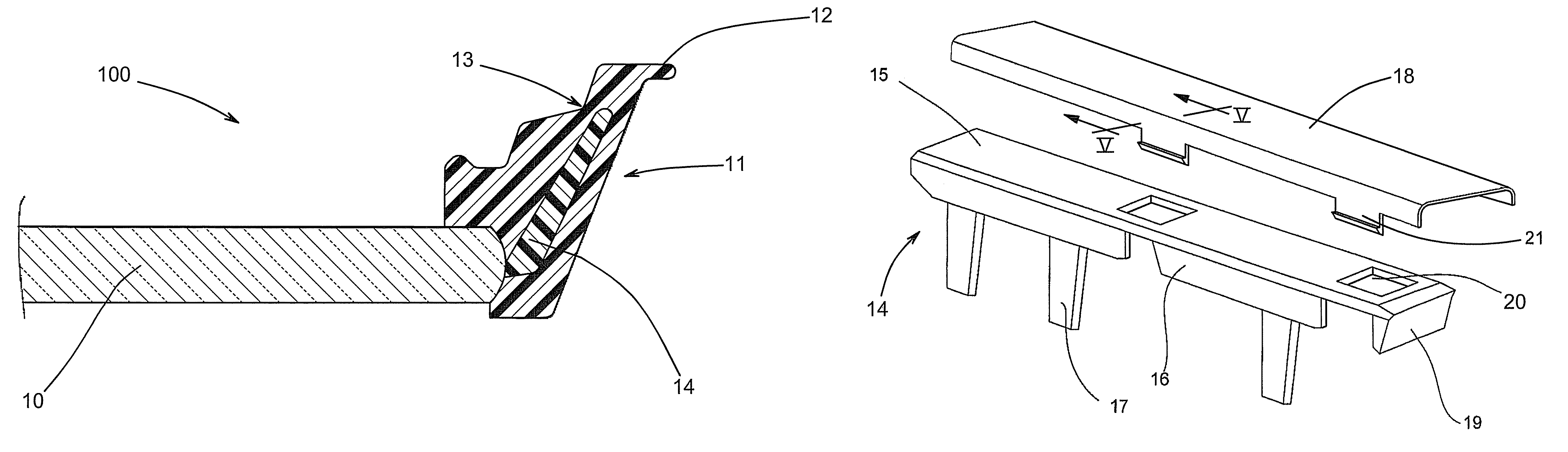
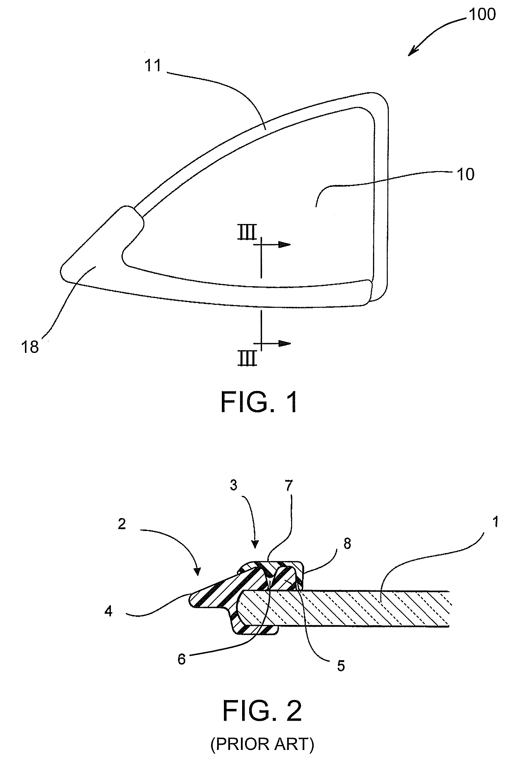
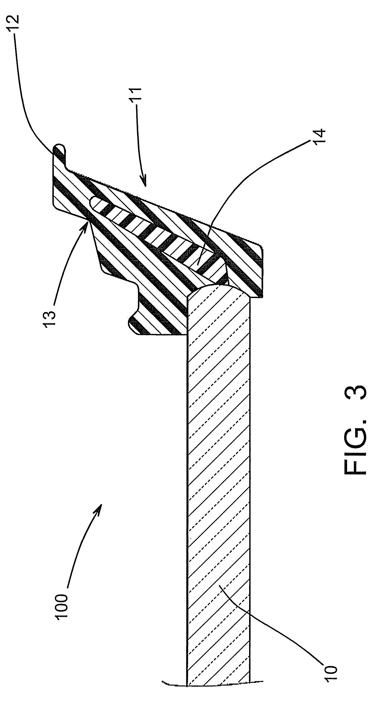
[0028]FIG. 1 is a schematic plan view of a vehicle glazing in accordance with the invention, and illustrating the positioning of a trim on the glazing, as viewed from the outside of the vehicle. The glazing represents a rear quarterlight, but may be any automotive glazing as described below. The glazing 100 comprises a pane 10 of glazing material which is provided with an edge-encapsulated glazing profile 11 which extends around the periphery of the pane. In this example, the edge-encapsulated glazing profile 11 is provided around the entire periphery of the pane. The pane 10 may be composed of glass or a suitable transparent durable plastics material. The lower portion of the periphery of the pane 10 is also provided with a trim 18, which extends along the entire lower edge of the pane 10 and partway up one side. The glazing 100 is fitted into an aperture in the bodywork of a vehicle (not shown), and retained in place by adhesive (not shown).

[0029]FIG. 2 is a schematic section of p...


PUM

PropertyMeasurementUnit
lengthaaaaaaaaaa
widthaaaaaaaaaa
flexibleaaaaaaaaaa

Abstract

A vehicle glazing has a glazing profile provided around at least a portion of the periphery of a pane of glazing material. A rigid insert is embedded in the glazing profile, and a trim is mounted on the glazing profile, the trim engaging the insert and being retained by it. The insert is provided with at least one aperture through which the insert is engaged by at least one protrusion on the trim.

Description

BACKGROUND OF THE INVENTION[0001]1. Field of the Invention[0002]The present invention relates to a vehicle glazing having a trim mounted thereon, and in particular it relates to a means of attachment of a trim to a glazing profile provided around at least a portion of the periphery of the glazing.[0003]2. Description of the Related Art[0004]Vehicle manufacturers strive to produce attractive vehicles, especially cars, since the aesthetic qualities of a car are important for commercial success. A number of features contribute to the overall appearance of a vehicle, one of which is the trim associated with the vehicle bodywork. In particular, trim may be provided on doors and windows, and is usually black or silver in colour. A finisher is an item of trim which may be mounted on a profile, other trim or on a glazing. Finishers may be made of metal, with a bright (i.e. silver) finish such as chrome-plating, but more usually they comprise plastic strips with a bright finish, possibly a m...

Claims


Application Information

Patent Timeline
Patent Type & Authority Patents(United States)
IPC IPC(8): B60J10/02B60J10/00B23P17/04
CPCB60J10/0051B60J10/02B60J10/0062Y10T29/49826B60J10/265B60J10/30B60J10/70
Inventor SENGE, CHRISTOPH
Owner PILKINGTON ITALA
Why Eureka
Try Eureka