Method and system for real-time volume rendering on thin clients via render server

a render server and volume rendering technology, applied in the field of medical imaging and image modalities, can solve the problems of inefficient transfer of inability to transfer large amounts of data, and inability to meet the requirements of patient care,

Active Publication Date: 2013-08-13
AGFA HEALTHCARE NV
View PDF17 Cites 63 Cited by
  • Summary
  • Abstract
  • Description
  • Claims
  • Application Information

AI Technical Summary

Problems solved by technology

As the amount of volume data has grown to GB of data, retrieving the data from the PACS server to the radiologist's workstation can take a substantial amount of time, i.e., several minutes.
The aging Digital Imaging and Communications in Medicine (DICOM) communication protocol standard is also not very efficient to transfer large amounts of data from the PACS server to the workstation.
Depending on the network bandwidth the transfer time can take even longer especially for 100 Mbit / s and slower networks.
Because the sheer amount of data to be processed, the radiologist's workstation has to be very powerful and it may require specialized hardware to accelerate the interactive viewing.
As hospitals don't upgrade their workstations very often, the workstation of the radiologist may be actually underpowered to view the large data sets efficiently.
These people may have even lower bandwidth network connections to the PACS server and their reviewing computer may have low computation specifications.
This may result in very long waiting times before the volume data is sent to the reviewing computer or because of the low computation power it may not even be possible to do the viewing at all.
This amount of data is far too much to be passed over typical hospital networks that have no ore than 100 Mbit / s bandwidth.

Method used


Image

  • Method and system for real-time volume rendering on thin clients via render server
  • Method and system for real-time volume rendering on thin clients via render server
  • Method and system for real-time volume rendering on thin clients via render server

Examples


Embodiment Construction

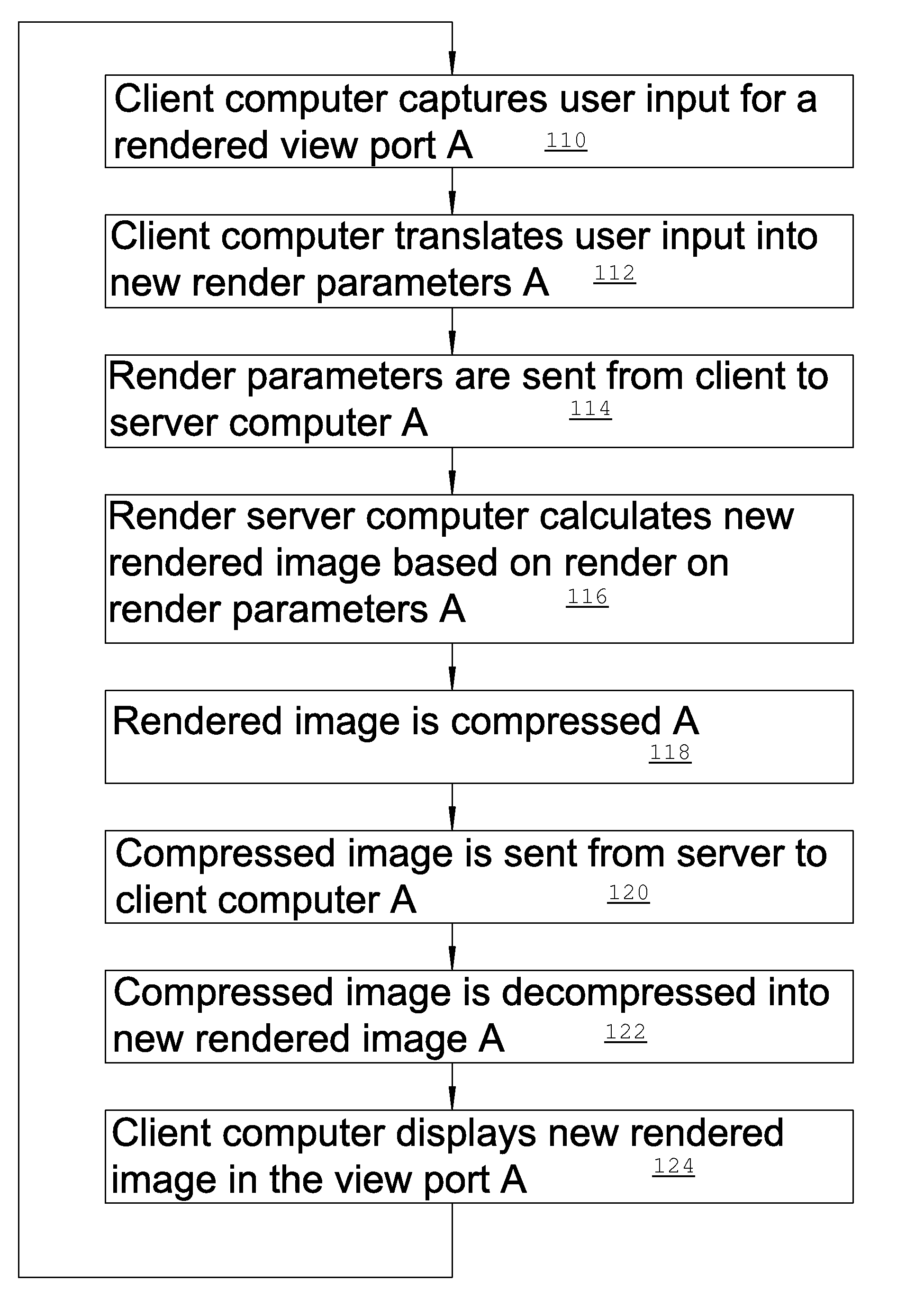
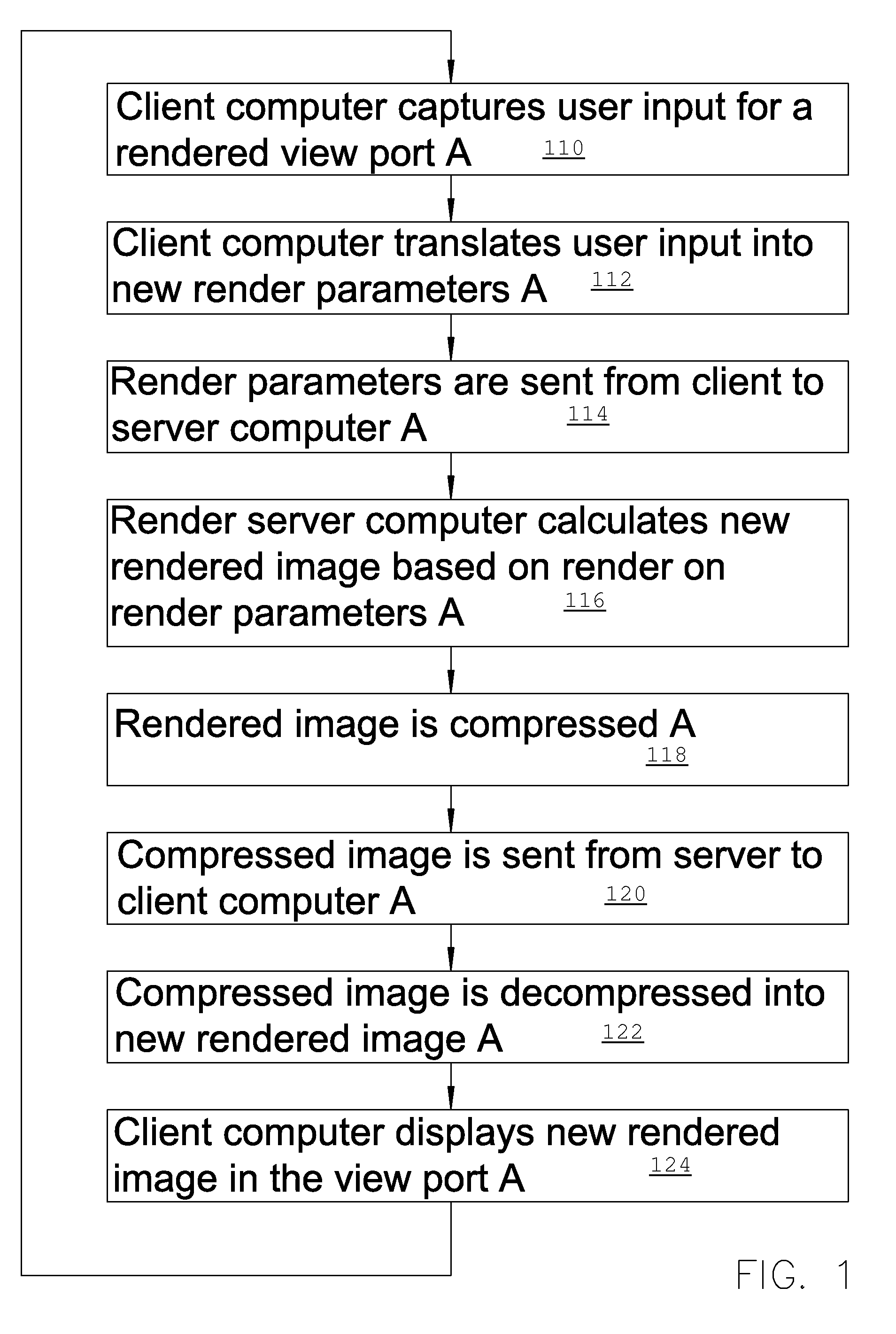
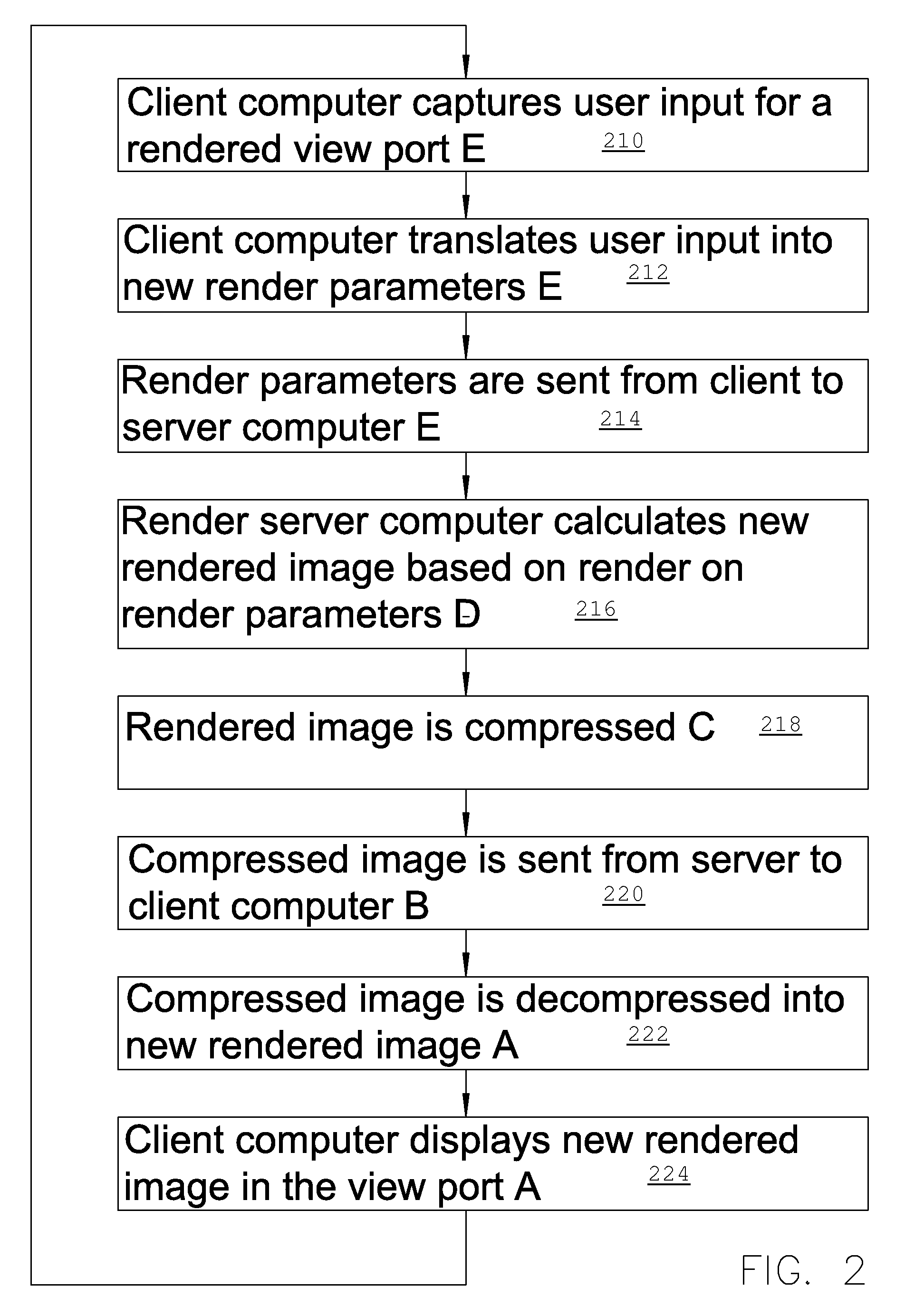
[0047]The exemplary set-up described below enables volume viewing and interaction on one or more client computers in one or more viewing ports making use of a render server computer and a compressed rendered video streaming technique. The volume data to view is only present on the server. For each viewing port there is a rendering and communication chain wherein the client sends a stream of rendering parameter sets from the client to the server. Each parameter set corresponds to one image the server has to render. Corresponding to the stream of received parameter sets the render server renders a stream of images. The stream of rendered images is compressed by a video compression scheme. Either lossy video compressions such as for example mpeg2 or mpeg4 or any form of lossless video compression may be applied. The video compressed stream of images is sent from the server to the client. The client decompresses the received video stream and displays the result into the viewing port.

[00...


PUM


Abstract

A method of server site rendering 3D images on a server computer coupled to a client computer wherein the client computer instructs a server computer to load data for 3D rendering and sends a stream of rendering parameter sets to the server computer, each set of rendering parameters corresponding with an image to be rendered; next the render computer renders a stream of images corresponding to the stream of parameter sets and the stream of images is compressed with a video compression scheme and sent from the server computer to the client computer where the client computer decompresses the received compressed video stream and displays the result in a viewing port. The rendering and communication chain is subdivided in successive pipeline stages that work in parallel on successive rendered image information.

Description

RELATED APPLICATIONS[0001]This application claims priority to European Patent Application No. EP 08102257.6, filed on Mar. 4, 2008, and claims the benefit under 35 USC 119(e) of U.S. Provisional Application No. 61 / 033,448, filed on Mar. 4, 2008, both of which are incorporated herein by reference in their entirety.BACKGROUND OF THE INVENTION[0002]In the field of medical imaging, image modalities keep producing ever larger and larger volume data sets. The latest computed tomography (CT) modalities produce volumes that can be very large. The last couple of year these multi-slice CT scanners have substantially increased their acquisition resolution. Single volume 3D data sets can now be in excess of one Giga Byte (GB) of data.[0003]Also the speed of capturing a single volume scan has increased dramatically. This enables the capture of several volumes of a patient at a time interval of a few seconds. This results in a time sequence of three dimensional (3D) data sets forming four dimensi...

Claims


Application Information

Patent Timeline
Patent Type & Authority Patents(United States)
IPC IPC(8): G06F15/16G06T1/20G06T15/00G06T15/08
CPCG06T15/005G06T15/08G06T1/20G06T2200/28G06T2210/52
Inventor VLIETINCK, JAN
Owner AGFA HEALTHCARE NV
Why Eureka
Try Eureka