
Wireless VoIP network for security system monitoring

a security system and wireless network technology, applied in the field of wireless network for security system monitoring, can solve the problems of limited success, dialup and other slow-speed connections may not work at all, and satellite uplinks may work

Inactive Publication Date: 2013-08-13
NUMEREX CORP
View PDF40 Cites 14 Cited by
  • Summary
  • Abstract
  • Description
  • Claims
  • Application Information

AI Technical Summary

Benefits of technology

[0015]The present invention is a mechanism for placing an alarm receiver (at security system central station) directly onto a private Voice-over-IP network shared by the customer, thereby eliminating the need for a Voice-over-IP system to re-dial the central station over a standard telephone line. Because both the security system and the alarm receiver are on the same Voice-over-IP network, and because neither end is connected to a standard telephone line (nor do alarm signals ever pass over standard telephone lines), errors are reduced dramatically, and overall response time is improved.
[0018]Alarm Broadband Network™ by NextAlarm™ was built to solve these problems. Alarm Broadband Network™ allows customers to enjoy the benefits and cost savings of Voice-over-IP service, while still allowing their alarm systems to accurately communicate with our monitoring centers.
[0024]If the consumer does not have Voice-over-IP service, they can still use Alarm Broadband Network™, so long as the consumer has Broadband Internet or other Internet connection. Even for customers who have regular telephone lines, Alarm Broadband Network™ offers the additional convenience of event reporting (such as opens and closes) in real-time without seizing a consumer's telephone line. In addition, Alarm Broadband Network™ offers the additional protection of Line Security, not available with standard telephone hookups.
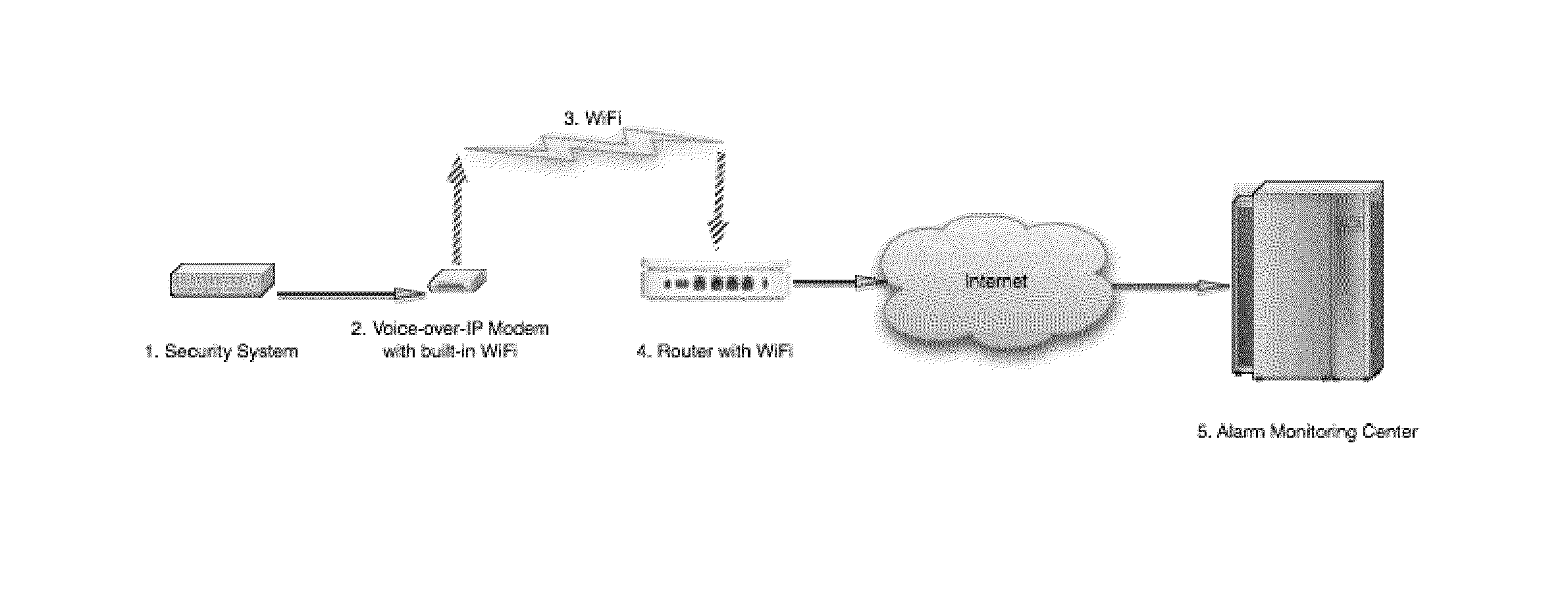
[0028]In the present invention, a wireless or Ethernet over A / C power component is described, such that the Voice-over-IP equipment can be placed at a distance from a router, without the need to run an Ethernet cable from the VoIP equipment to the router. This arrangement is useful, as in many cases, the customer's security system is hidden within a closet, or else placed within the home or business at a significant distance from their Internet connection and router. The present invention accomplishes this by adding a built-in WiFi (wireless) radio, or a built-in Ethernet over Power circuit, into the Voice-over-IP equipment installed in the home or business.

Problems solved by technology

Other connections, such as satellite uplinks may work, with some limited success.
Dialup and other slow-speed connections may not work at all.
However, users have reported problems when attempting to use VoIP with fax machines, modems, credit card “swipe” machines, and alarm systems.
Voice-over-IP service may impact the reliability of a security (alarm) system by interfering with its ability to report alarms to a consumer's monitoring station.
Although Voice-over-IP services are excellent for voice communication, they may not be suited for transmitting alarm system data to an alarm monitoring company.
As a result, many alarm monitoring companies simply do not accept customers who use Voice-over-IP.
Some consumers report that their alarm systems will work with VoIP, while others have difficulty.
Thus, using an alarm system with VOIP service is a recognized problem in the art.
Many users of alarm systems, credit card swipe machines, and the like, report problems when attempting to use such hardware with VoIP systems.
The apparatus may dial the wrong number, or the system might not provide the proper bandwidth or signal clarity to properly send the necessary signals to the central station or dialed number.
Similar problems can occur when using Prior Art fax machines and other communications devices (e.g., 56K dialup modems and the like) with VoIP networks.
These types of errors may occur due to multiple layers of translation back and forth between digital (Internet technology), and analog (telephone) system.
As a result, alarm and other types of signals are frequently incorrectly received.
However, such higher bandwidth lines require a consistently robust broadband connection and can slow down other users on the broadband connection.
In addition, even if an alarm system can be made to work with an existing VoIP telephone network, the system suffers from the same problem as Prior Art dialup service.
Namely, when the alarm dials out, it seizes the phone line, making it impossible for the consumer to call out at the same time.
In an emergency or even in the event of a false alarm, this can be frustrating or even dangerous.
If the alarm is trying to dial out, and the consumer is trying to contact 911, each may end up blocking the other.
In a false alarm scenario (where the consumer is trying to cancel the alarm) this may be merely frustrating.
In a medical or other emergency, it may be disastrous.
Prior Art alarm systems are also limited in many regards in that by using dialup communications, they cannot be monitored in real time.
If a burglar disables an alarm system, the alarm company may have no way of knowing the system is off-line.
In practice, this may mean that 24 hours or more may elapse before a malfunctioning or disabled alarm is detected and reported.

Method used


Image

  • Wireless VoIP network for security system monitoring
  • Wireless VoIP network for security system monitoring
  • Wireless VoIP network for security system monitoring

Examples


Embodiment Construction

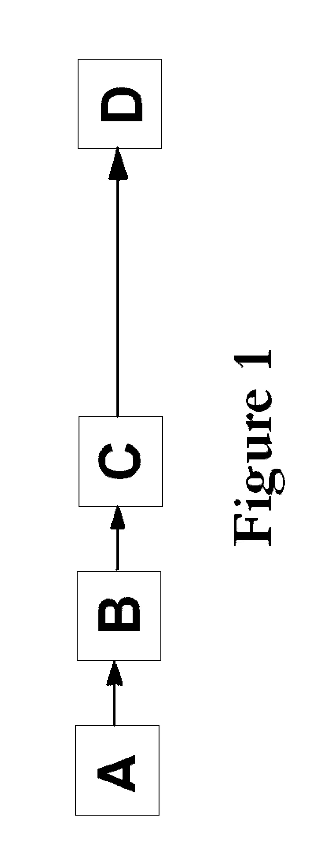
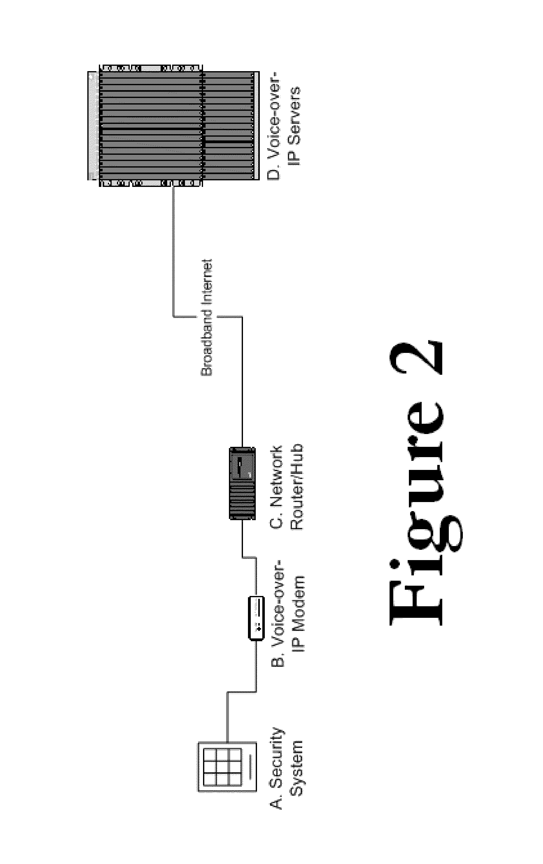
[0035]Voice-over-IP telephone services are typically offered in the following fashion as illustrated in FIGS. 1 and 2. The blocks in FIGS. 1 and 2 may be defined as follows. [A] represents Telephone equipment (such as a phone, a fax machine, or a home security system) is plugged into. [B] represents a VoIP modem (Voice-over-IP modem), a (typically) sub-$100 device that includes a telephone port and an Ethernet port. The VoIP modem is plugged via Ethernet into [C] a hub or router in the home or office, which is connected to the Internet via Broadband.

[0036]Once connected to the Internet, the VoIP modem [B] communicates with [D] a VoIP server or servers, at a remote facility (and usually operated by VoIP companies), which offers telephone services to its customers who connect to it using VoIP modems [B].

[0037]The VoIP modem then connects to a remote server over the Internet, while also offering a dial tone to the telephone device plugged into it. People who have alarm systems in their...


PUM


Abstract

A Voice over IP (VoIP) module is used to connect an alarm system to a monitoring station over the Internet. A built-in wireless or Ethernet over A / C power component is described, such that the Voice-over-IP equipment can be placed at a distance from a router, without the need to run an Ethernet cable from the VoIP equipment to the router. This arrangement is useful, as in many cases, the customer's security system is hidden within a closet, or else placed within the home or business at a significant distance from their Internet connection and router. The present invention accomplishes this by adding a built-in WiFi (wireless) radio, or a built-in Ethernet over Power circuit, into the Voice-over-IP equipment installed in the home or business.

Description

CROSS-REFERENCE TO RELATED APPLICATIONS[0001]The present application is a Continuation-In-Part application of U.S. patent application Ser. No. 12 / 018,724 (ELLIOT-0008), filed on Jan. 23, 2008 and incorporated herein by reference, which in turn is a Continuation-In-Part of U.S. patent application Ser. No. 11 / 517,025 (ELLIOT-0007), filed on Sep. 7, 2006, and incorporated herein by reference; which in turn is a Continuation-In-Part of U.S. patent application Ser. No. 11 / 226,857 (ELLIOT-0005) filed on Sep. 14, 2005 and incorporated herein by reference; patent application Ser. No. 11 / 226,857 in turn claims priority from Provisional U.S. patent application Ser. No. 60 / 651,662 (ELLIOT-0004) filed on Feb. 11, 2005 and incorporated herein by reference; patent application Ser. No. 11 / 226,857 is also a Continuation-In-Part (CIP) of co-pending application Ser. No. 10 / 861,790 (ELLIOT-0003), filed on Jun. 7, 2004, and incorporated herein by reference; patent application Ser. No. 11 / 226,857 is in ...

Claims


Application Information

Patent Timeline
Patent Type & Authority Patents(United States)
IPC IPC(8): H04M11/00H04M11/04
CPCH04L12/40013H04L12/413G08B27/005H04M11/04H04L65/1013H04L12/66
Inventor ELLIOT, HARVEY ALEXANDERFIELD ELLIOT, BRYANELLIOT, DANIEL J.
Owner NUMEREX CORP
Learn More