Method for detecting underground tunnels

a tunnel detection and underground technology, applied in the field of underground tunnel detection, can solve the problems of detection technologies and methods that struggle with such determinations, and achieve the effects of reducing the clutter in the gravity gradient vector, reducing delays and false readings, and reducing false readings

Active Publication Date: 2013-08-13
RAYTHEON CO
View PDF1 Cites 4 Cited by
  • Summary
  • Abstract
  • Description
  • Claims
  • Application Information

AI Technical Summary

Benefits of technology

[0006]According to one embodiment of the present disclosure, a method for detecting underground tunnels is presented having a series of steps that comprises first calculating a plurality of gravity gradient vector field pairs for an area, each gravity gradient vector field pair being comprised of two vector fields that are orthogonal to one another. Next, a probability tomography analysis for source pole occurrence probability (SPOP) is performed on each of the plurality of gravity gradient vector field pairs. After performing the probability tomography analysis, the dipolar points and polar source points in each gravity gradient vector field pair are then detected. From the detected polar source points, the polar source points that are present in one but not in both of the two vector fields for each of the plurality of gravity gradient vector field pairs are identified to thereby detect the tunnels. Detection of tunnels in accordance with the teachings of the present disclosure may serve to alleviate some of the delays and false readings currently being experienced with the technologies and methods used today in the industry. Still further, tunnel detections in accordance with the teachings of the present disclosure may provide a more revealing tunnel signature.
[0007]In one embodiment of the present disclosure, the gravity gradient vector field pairs may be calculated from the horizontal tensor gravity gradients for the area in question and then processed to estimate the source pole occurrence probability based on the gravity of equivalent masses. By utilizing a probability tomography analysis to estimate the source pole occurrence probability for each of the gravity gradient vector fields in each pair, the subsurface density variations (SSDV), i.e., clutter, commonly experienced with the use of other technologies may be greatly reduced thereby providing for more efficient and reliable tunnel detections.
[0008]Accordingly, some embodiments of the disclosure may provide numerous technical advantages. Some embodiments may benefit from some, none or all of these advantages. For example, a technical advantage of one embodiment of the disclosure may be the reduction of clutter in the gravity gradient vector field pairs. Furthermore, the reduction of clutter in the resulting gravity gradient vector field pairs may provide for faster tunnel detection rates as well as provide a reduced occurrence of false readings. Still further, the reduction of clutter may provide a more enhanced and recognizable tunnel signature that depicts the actual tunnel orientation.
[0009]Another example of a potential technical advantage of one embodiment of the present disclosure is that it may provide the ability to more readily distinguish surface features responsible for generating tunnel-like signatures from the signatures of actual tunnels. Many current tunnel detection technologies and methods struggle with such determinations due to the extent of distortion and clutter present within their readings.

Problems solved by technology

Many current tunnel detection technologies and methods struggle with such determinations due to the extent of distortion and clutter present within their readings.

Method used


Image

  • Method for detecting underground tunnels
  • Method for detecting underground tunnels
  • Method for detecting underground tunnels

Examples


Embodiment Construction

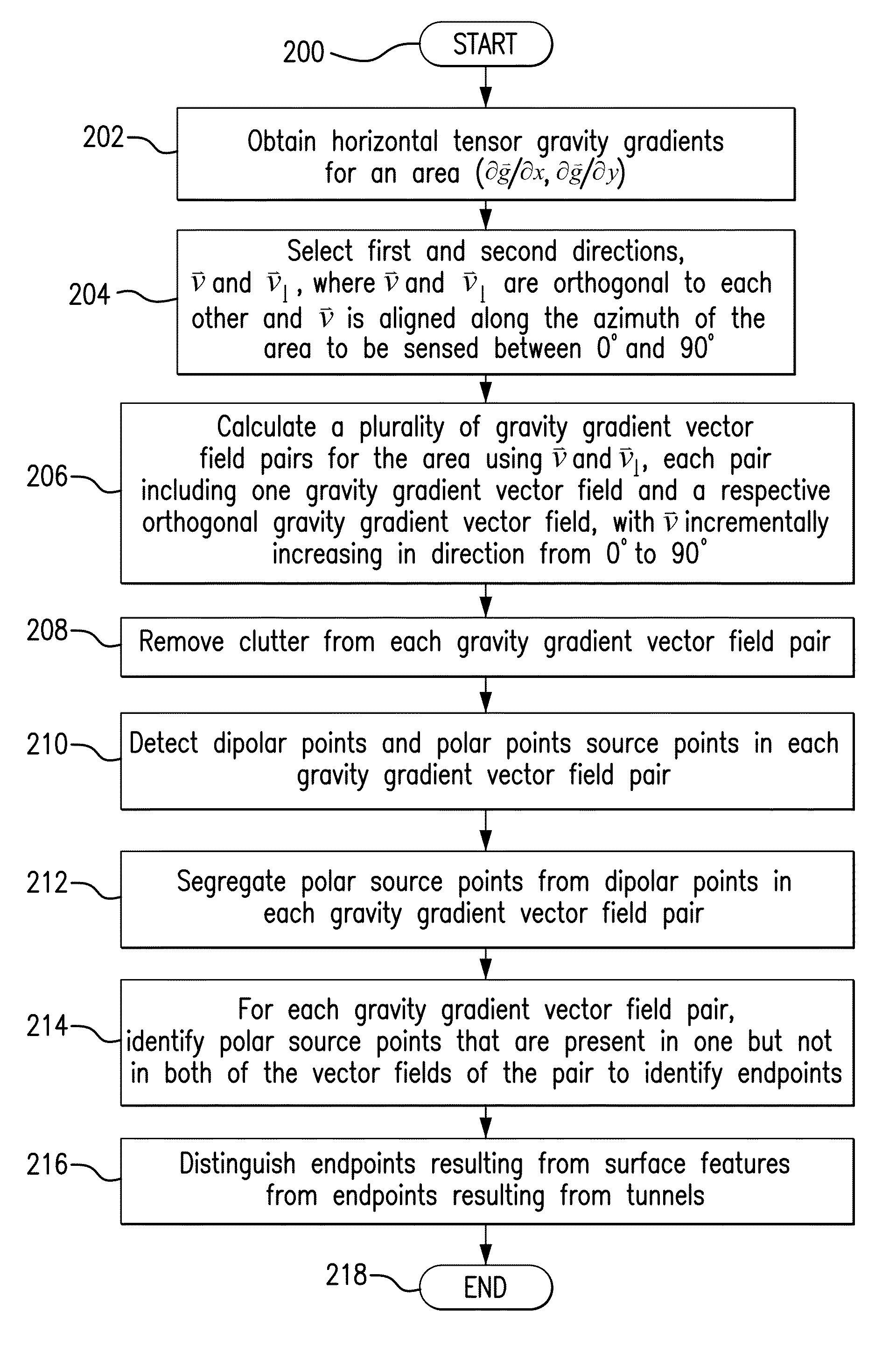
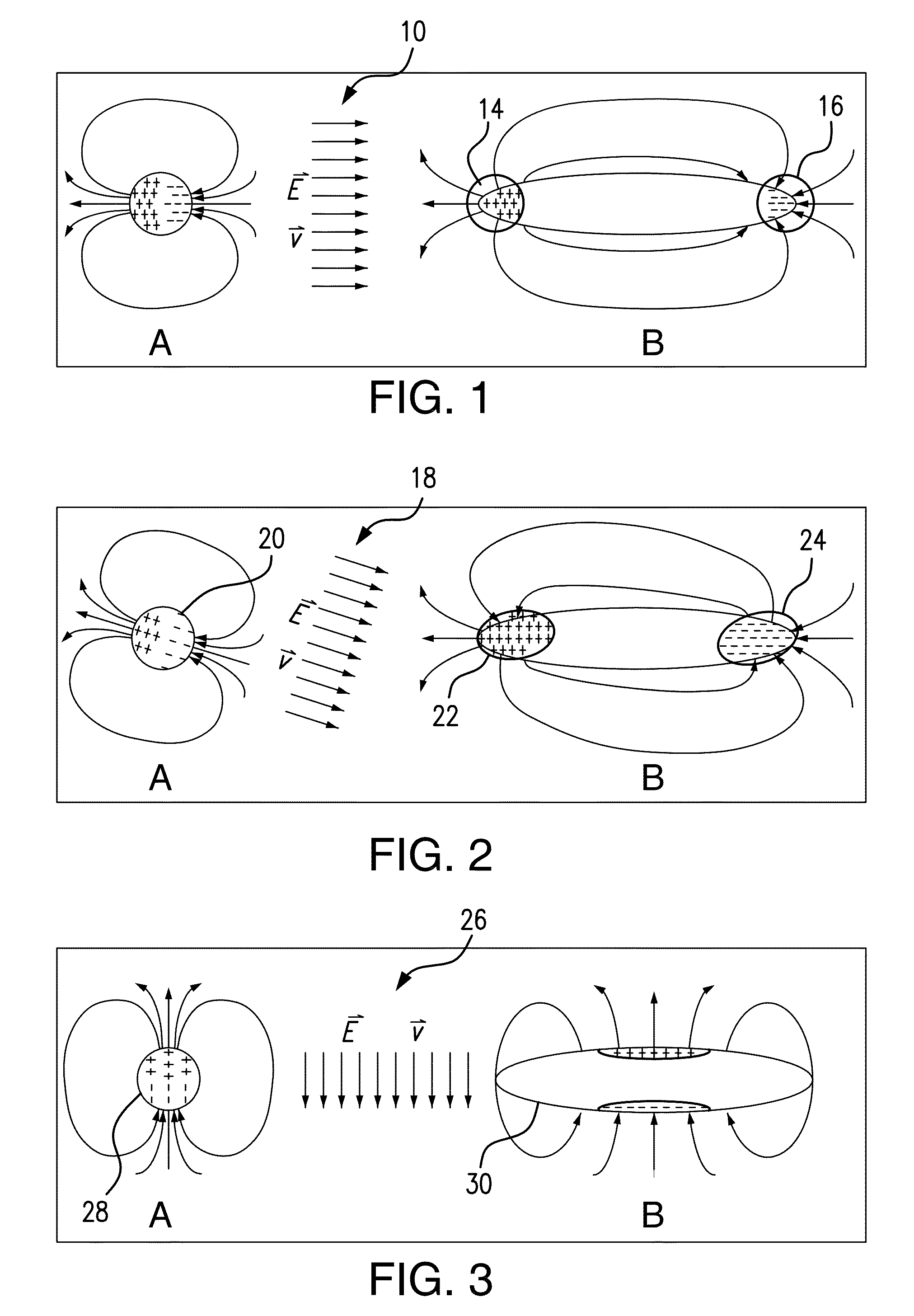
[0019]Borrowing from conventional electrostatic field theory, the gravity gradient of a localized (spherical) mass anomaly is a conventional dipole field. It can be shown that gravity field gradient (∂g / ∂ν) with respect to a fixed direction ν is equivalent to the electrical field distribution if: 1) a uniform electrical field is applied in the direction parallel to the direction of ν; and 2) every mass is replaced with a dielectric with permittivity equal to that mass. Further, the “gravity dipole moment” of a mass anomaly is always oriented along the direction of the gravity gradient. From these principles, if a long tunnel is viewed as a collection of voids when exposed to a gravity gradient field, all gravity dipole moments cancel except for two equivalent masses located at the tunnel endpoints. These equivalent masses have equal and opposite sign. Hence, to distinguish the signature of a tunnel from localized small voids and other subsurface density variations (SSDVs), i.e., clu...


PUM


Abstract

A method for detecting tunnels within an area comprising in one embodiment the steps of providing horizontal tensor gravity gradients for the area, calculating a plurality of gravity gradient vector field pairs from the horizontal tensor gravity gradients, each gravity gradient vector field pair including one gravity gradient vector field and a respective orthogonal gravity gradient vector field, detecting dipolar points and polar source points in each of the one and respective orthogonal gravity gradient vector fields for each gravity gradient vector field pair, identifying the polar source points that are present in one but not in both of the one gravity gradient vector field and the respective orthogonal gravity gradient vector field for each gravity gradient vector field pair to identify endpoints, and distinguishing the endpoints resulting from surface features from the endpoints resulting from tunnels. The polar source points form the endpoints of the tunnels.

Description

TECHNICAL FIELD OF THE DISCLOSURE[0001]This disclosure relates generally to the detection of underground voids. More particularly, this disclosure relates to a method for detecting underground oblong voids indicative of tunnels.BACKGROUND OF THE DISCLOSURE[0002]The detection of underground voids is an area of growing importance within the mining, oil and gas, construction, and defense industries. For example, as with construction, the detection of old underground tunnels is necessary in areas where buildings are being built. Further to this point, the detection of water mains made of wood or concrete, as well as old collapsed basements or storage tanks is equally required during construction projects. In general, there is an ever-growing need for new and improved ways to detect underground tunnels of various sorts. Currently, beyond detections made visually at the ground site, underground tunnel detections are attempted by way of a variety of single sensor and multi-sensor approache...

Claims


Application Information

Patent Timeline
Patent Type & Authority Patents(United States)
IPC IPC(8): G01V3/38G01B7/00
CPCG01V7/00
Inventor DOLGIN, BENJAMIN P.DAVIS, CLAYTON P.
Owner RAYTHEON CO
Why Eureka
Try Eureka