Traction drive system

a technology of traction drive and drive shaft, which is applied in the direction of couplings, slip couplings, gearing, etc., can solve the problems of damage to drivetrain components or motors providing power to the arm, robot arms for vending machine applications, and inability to provide a mechanism to allow the arm to move, etc., to achieve high precision movement, reduce backlash, and reduce the effect of the ratio of ratios

Active Publication Date: 2013-08-20
QUANTUM MOTION LLC
View PDF56 Cites 4 Cited by
  • Summary
  • Abstract
  • Description
  • Claims
  • Application Information

AI Technical Summary

Benefits of technology

[0007]The traction drive system can function in the following manner: the array of traction balls can be loaded between the input drive disk and traction plate with a clamping device; in some embodiments the traction plate can be fixed rotationally with respect to the input drive disc, traction balls, spider, and output drive shaft; as the input drive disk is rotated, the array of traction balls can roll in a circular path on both the surface of the input drive disk and the surface of the traction plate; the traction balls may be sufficiently constrained to prevent deviation from the circular path; since the traction plate can be rotationally fixed, the array of traction balls can rotate in the same direction as the drive pulley at a lower resultant speed, such as ½ the speed of the input drive disk; the traction balls can contact the spokes of the spider and transfer their circular motion to the spider; the spider can be fixed to the output drive shaft and, therefore, the spider rotation can be transmitted directly to the output drive shaft; the resulting output shaft speed can be lower than the input drive disk speed, such as ½ the input drive disk speed. In other embodiments, the output drive shaft can be fixed rotationally with respect to the input drive disc and traction plate.
[0014]One feature of the novel traction drive system is that it can act as an overload or safety clutch. The controllable and predictable slippage reduces the risk of damage to the drivetrain components and motor. If, for example, the output drive shaft's rotational motion seizes or is abruptly reversed, the slippage would prevent damage to the powertrain components coupled to the input drive disk. Similarly, the traction drive allows the output shaft or an arm segment carrying the traction drive to be manually rotated without risk of damage to the drive components. In addition, the slippage also provides a safety feature to reduce the potential for injury to objects that may come into contact with the arm.
[0016]The traction drive system can provide a reduction in backlash over traditional gear and belt drive systems. The traction drive is inherently backlash free, and because of the manner in which the traction balls transmit rotational motion, it can have an inherent 2:1 reduction ratio.
[0017]The absolute rotational position sensor system can provide true absolute position feedback of an articulated robotic arm. The absolute position feedback allows high precision movement of an articulated robotic arm. Additionally, the absolute rotational position sensor system can allow a robotic arm to be programmed for single position calibration. For example, a program with a number of predefined positions can be loaded into a controller, such as a vending machine controller, and by orienting the robotic arm to single calibration position, the robotic arm can be automatically programmed to all predefined locations.

Problems solved by technology

Previously, robotic arms for vending machine applications and the like did not provide a mechanism to allow robotic arm members to move independently from the motor driving the arm member.
Therefore, if the movement of the arm member halts due to a collision or jam, or is abruptly reversed, damage to drivetrain components or the motor providing power to the arm is possible.
Manual movement of the robotic arm members may also damage the drivetrain components or the motor.
Furthermore, previous robotic arms utilize non-absolute position encoders to provide position feedback to the vending machine control.

Method used


Image

  • Traction drive system
  • Traction drive system
  • Traction drive system

Examples


Embodiment Construction

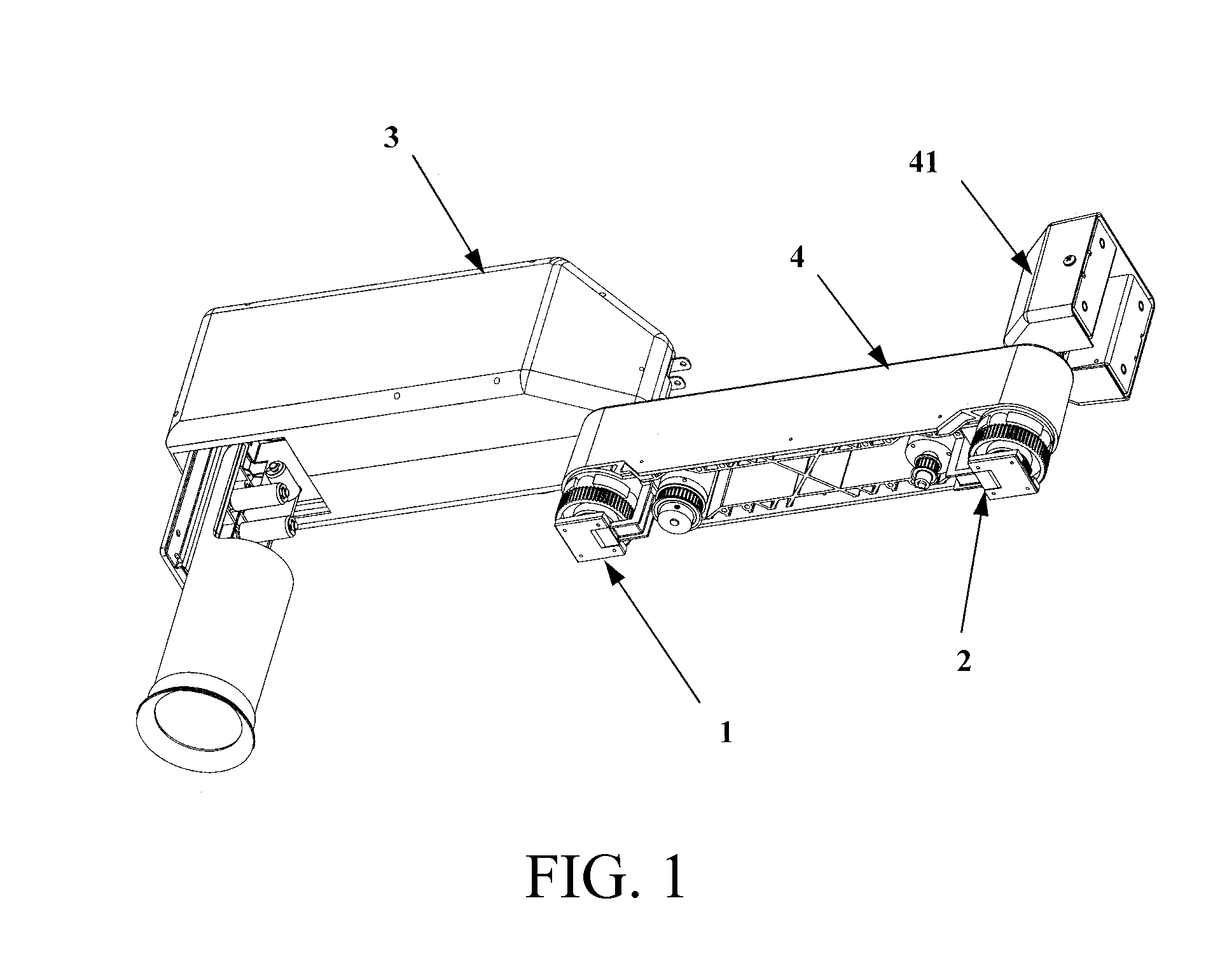
[0023]Referring to FIG. 1, the utilization of two traction drive systems 1 and 2 are shown in an articulated robotic arm. The first traction drive system 1 is assembled in an arm segment 4 and directly rotates arm segment 3 relative to arm segment 4. The second traction drive system 2 is assembled to arm segment 4 and rotates arm segment 4 relative to arm segment 41, which can be a fixed base feature of the articulated robotic arm. It will be appreciated that any suitable number of traction drive systems may be applied to an articulated robotic arm to move any suitable number of arm segments in any suitable directions.

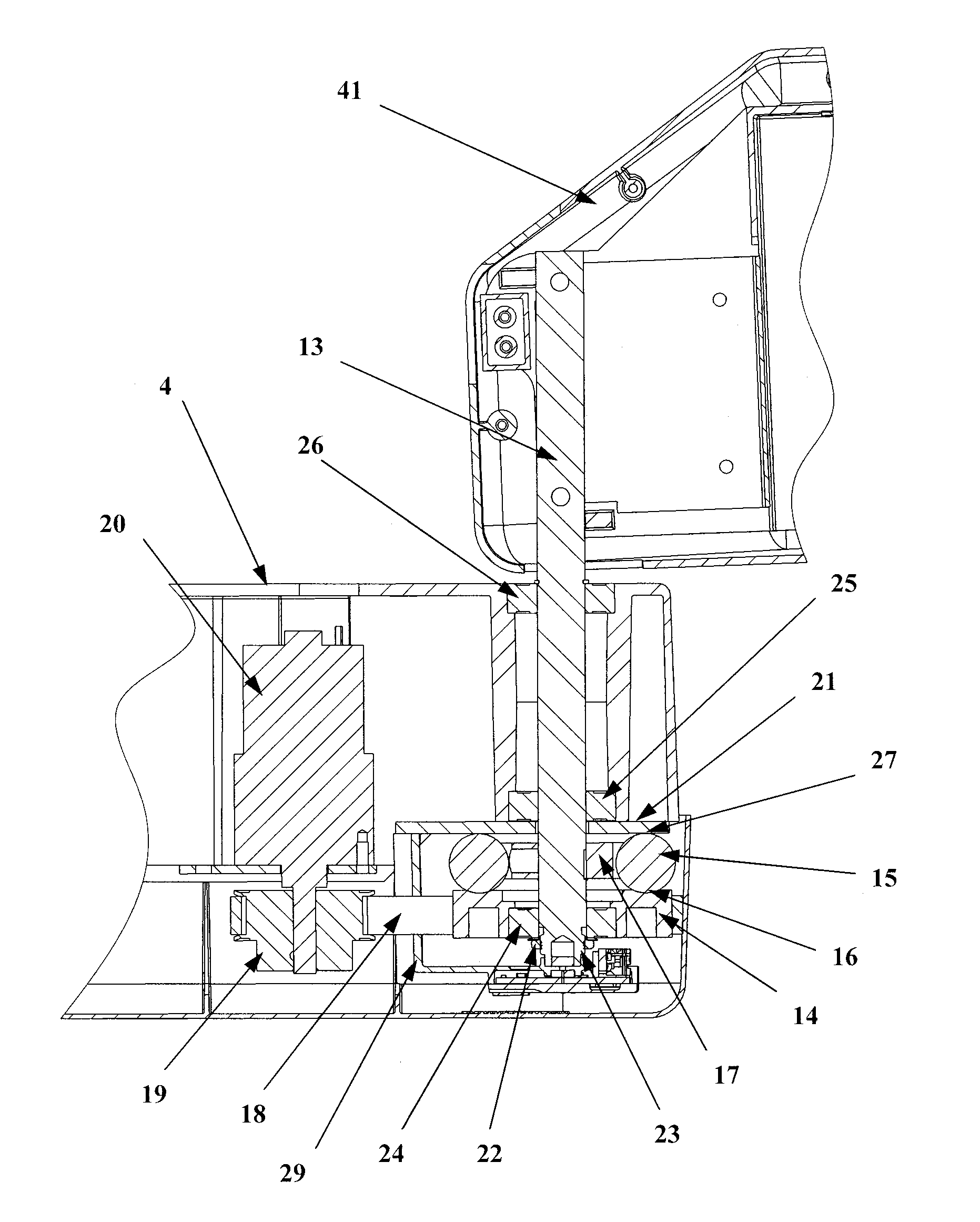
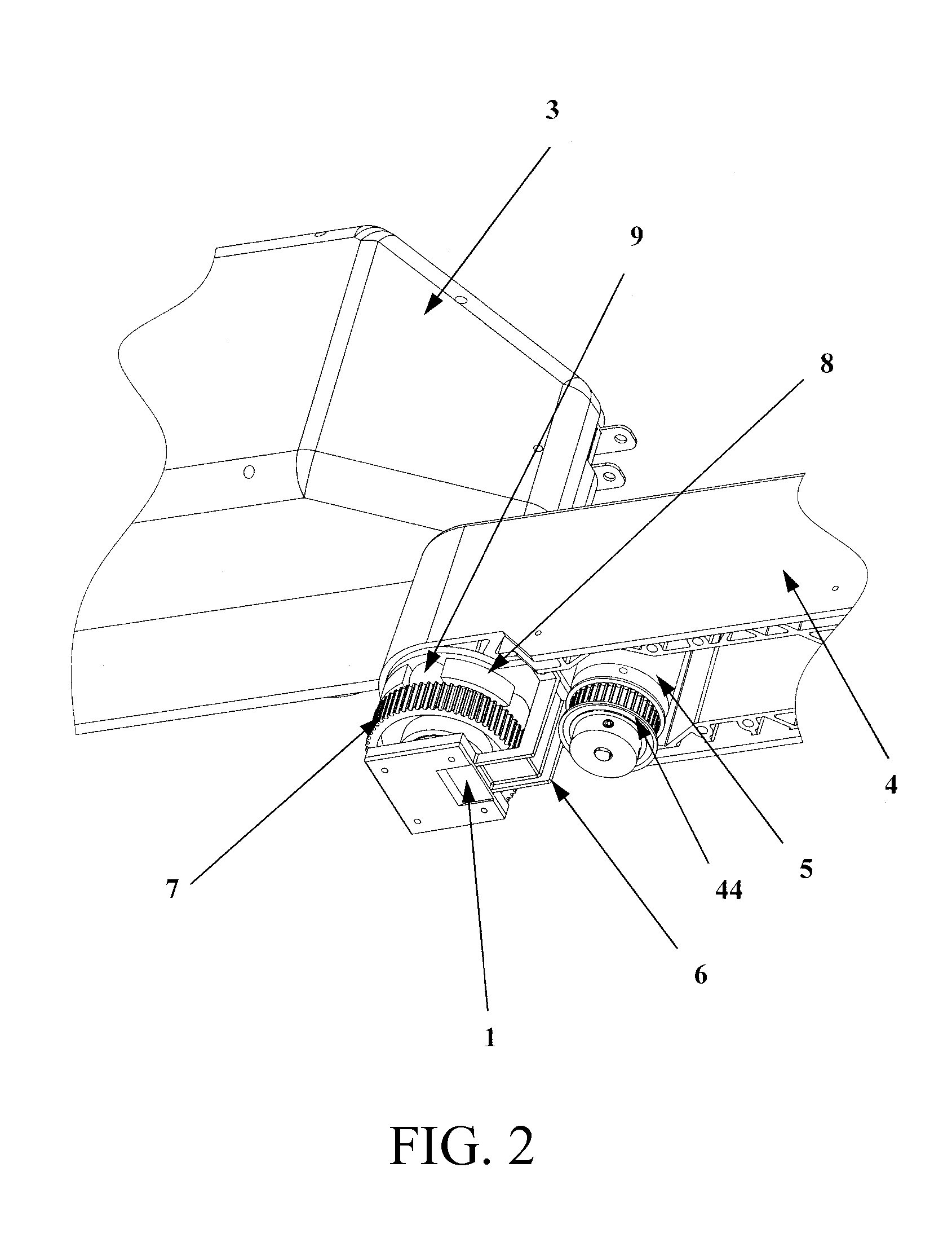
[0024]Referring to FIG. 2, the traction drive system 1 is shown at the joint of two articulated robotic arm segments. The traction drive system 1 is assembled to arm segment 4 and provides rotational motion to arm segment 3 relative to arm segment 4. As shown, the traction drive system 1 can include an input drive disk 7, a spider 8, and traction balls 9. A mounting br...


PUM


Abstract

A traction drive system for an articulated robotic arm. The traction drive system can include an input drive disk, a spider, an array of traction balls, a traction plate, an output drive shaft, a clamping device to load the traction balls, and an absolute rotation position sensor system. The rotation of the output drive shaft can be coupled to the rotation of the input drive disk while the traction balls are frictionally engaged to the drive disk surface and traction plate surface. The rotational connection can be decoupled when the traction balls are not frictionally engaged to the drive disk surface and traction plate surface. A rotational position sensor located in proximity to the traction drive can provide absolute rotational position feedback of the output drive shaft.

Description

CROSS-REFERENCE TO RELATED APPLICATIONS[0001]This patent application claims the benefit of U.S. Provisional Patent Application No. 61 / 172,110, filed Apr. 23, 2009, which is incorporated by reference in its entirety herein.BACKGROUND[0002]Previously, robotic arms for vending machine applications and the like did not provide a mechanism to allow robotic arm members to move independently from the motor driving the arm member. The movement of arm members of prior art are permanently coupled to their respective driving motors. Therefore, if the movement of the arm member halts due to a collision or jam, or is abruptly reversed, damage to drivetrain components or the motor providing power to the arm is possible. Manual movement of the robotic arm members may also damage the drivetrain components or the motor.[0003]Personal safety is also a concern because there is no mechanism to disengage the movement of the robotic arm member from the motor, and the motor will continue to drive the moti...

Claims


Application Information

Patent Timeline
Patent Type & Authority Patents(United States)
IPC IPC(8): F16H13/08
CPCB25J9/102F16D7/005F16H13/08Y10T74/20317F16D2300/18
Inventor UBIDIA, FERNANDO A.STEIN, AARON M.LEWIS, JOHN
Owner QUANTUM MOTION LLC
Why Eureka
Try Eureka