Rotating object dynamic balancing system and method

a dynamic balancing and rotating object technology, applied in the direction of propellers, propulsive elements, water-acting propulsive elements, etc., can solve the problems of increasing vibration, undesirable effects, and never perfectly balanced rotating machinery, and achieves low manufacturing cost and low price of sale , easy and efficient manufacturing and marketing

Inactive Publication Date: 2013-08-27
FORTUNE DOUG +1
View PDF67 Cites 12 Cited by
  • Summary
  • Abstract
  • Description
  • Claims
  • Application Information

AI Technical Summary

Benefits of technology

[0024]It is another object of the present invention to provide a new and improved rotating object dynamic balancing system that may be easily and efficiently manufactured and marketed.
[0025]An even further object of the present invention is to provide a new and improved rotating object dynamic balancing system and method that has a low cost of manufacture with regard to both materials and labor, and which accordingly is then susceptible of low prices of sale to the consuming public, thereby making such rotating object dynamic balancing system and method economically available to the buying public.
[0027]Even still another object of the present invention is to provide a rotating object dynamic balancing system and method for dynamically balancing a propeller. This allows for the propeller to be easily, effectively and dynamically balanced, thereby reducing vibration, noise, and damage due to vibration fatigue.

Problems solved by technology

Rotating machinery is never perfectly balanced, and inevitably with the passage of time and use, increasing imperfections of balance cause increasing levels of vibration.
Increasing vibration leads to undesirable effects, such as power loss, increased noise, increased wear and early failure of components.
It is also known that rotating objects generate great vibrations when the speed of the rotating object reaches a resonant speed (i.e., when the rotating object speed coincides with a natural frequency of the rotating system).
The resulting blades often deviate somewhat from the desired profile, which results in small, but nonetheless undesirable, differences in hydrodynamic performance among the blades.
An important disadvantage of statically balancing the blades in sets is that they have to be installed and used in matched sets.
Furthermore, balanced blades can be damaged during use by impacting an object by wear, by corrosion, marine growth, repainting or repairing, and therefore place the blades in an unbalanced state.
Such operations are costly and time consuming and require inactivation of the ship for some period of time.
While the above-described devices and repair procedures fulfill their respective objectives to partially or substantially correct imbalances due to damage or wear, the repairs are static and therefore do nothing to further counteract subsequent sources of imbalances, they do not describe a rotating object dynamic balancing system and method that allows for unattended and automatic dynamic balancing of any hub mounted blade, and in particular the unattended and automatic dynamic balancing of a marine propeller.

Method used


Image

  • Rotating object dynamic balancing system and method
  • Rotating object dynamic balancing system and method
  • Rotating object dynamic balancing system and method

Examples


Embodiment Construction

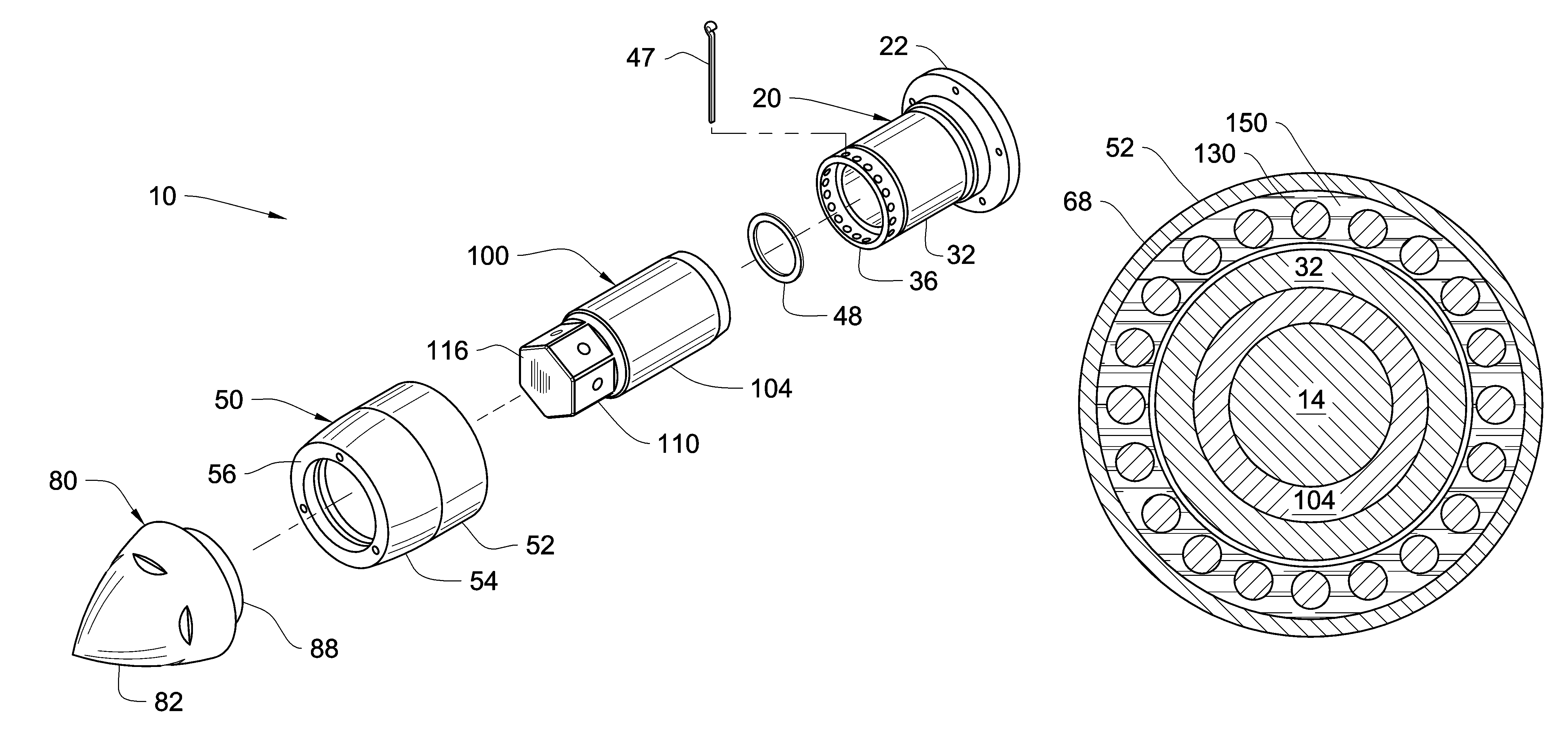
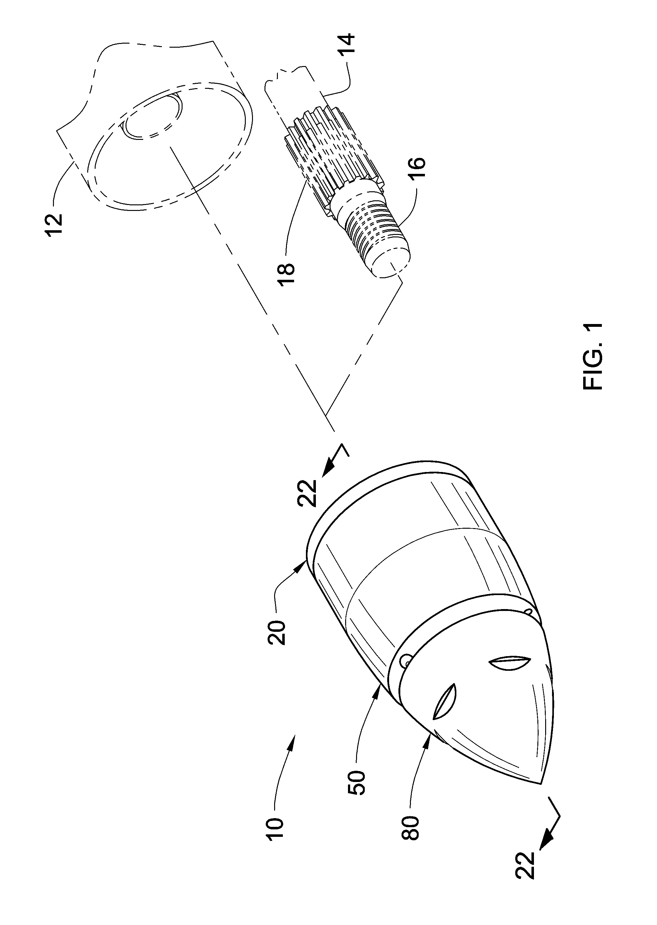
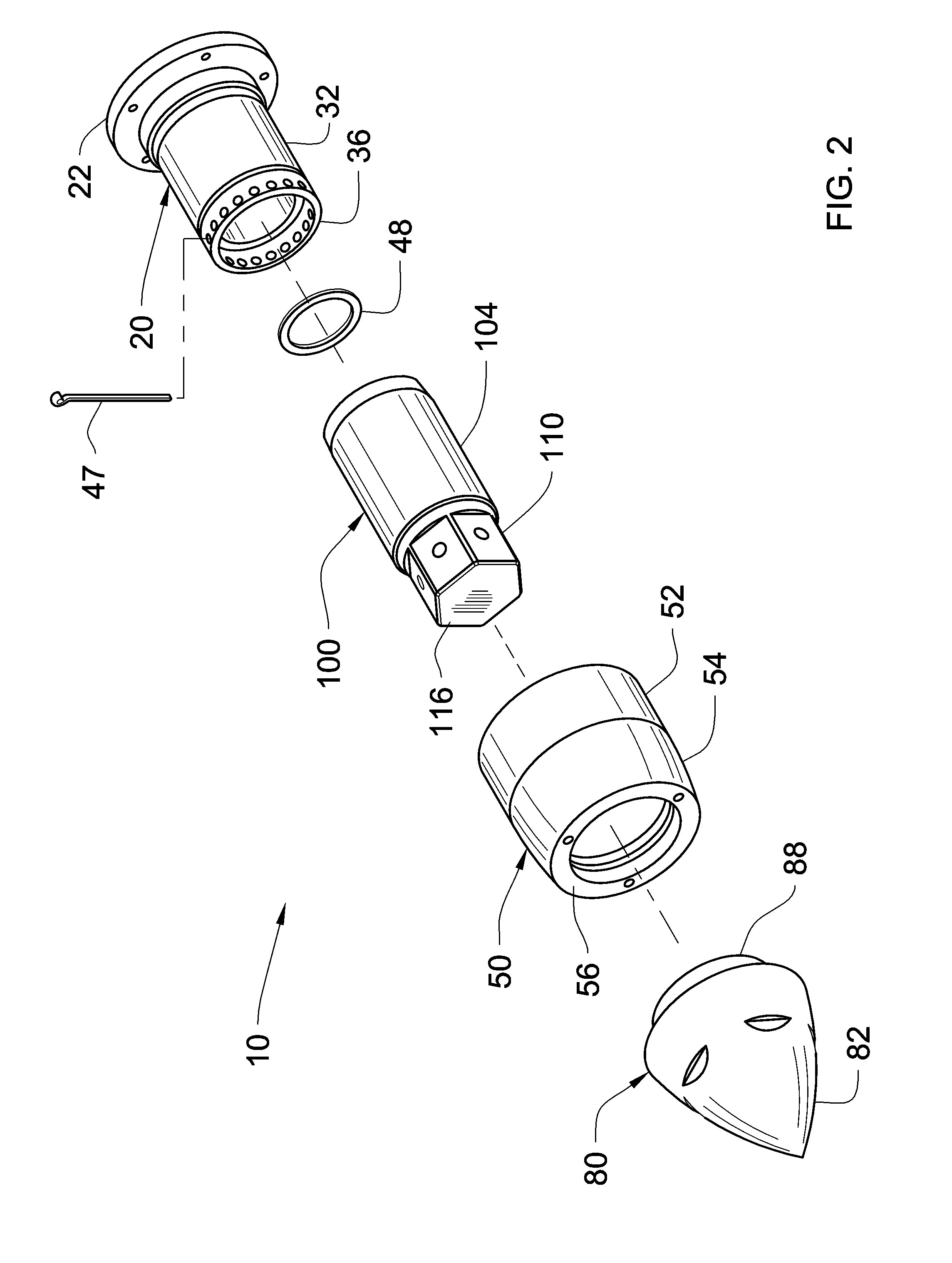
[0061]Referring now to the drawings and particularly to FIGS. 1-29, an embodiment of the rotating object dynamic balancing system and method of the present invention is shown and generally designated by the reference numeral 10.

[0062]In FIG. 1, a new and improved rotating object dynamic balancing system 10 of the present invention for dynamically balancing a rotating object 12 having a rotating shaft 14, is illustrated and will be described. The rotating object 12 can be, but not limited to, a boat or marine propeller, an aircraft propeller, a fan, impeller, mixer, wheel or hub, or any rotating object mounted on or driven by a shaft. More particularly, the rotating object dynamic balancing system 10 has an inner body assembly 20, an outer body assembly 50, a tail cone assembly 80, and a fastening body assembly 100 (illustrated in FIG. 2). The shaft 14 can include at least, as such with but not limited to an outboard or stern drive marine engine and propeller system, a threaded secti...


PUM


Abstract

A rotating object dynamic balancing system and method for balancing a rotating object including a shaft by using centrifugal force on a plurality of weighted masses traveling along at least one race. The rotating object dynamic balancing system has an inner body, an outer body, a fastening body or fastening body, and a plurality of weighted masses. The inner body has a hollow interior area and an aperture in communication with the interior area and adapted to receive the shaft. The outer body has a hollow interior area defined therethrough, and at least one radial race defined in the interior area. The outer body is attachable to the inner body. The fastening body has a hollow interior area, and is configured to be received into the interior area of the inner body. The interior area of the fastening body assembly is adapted to engage with the shaft received through the inner body thereby securing the rotating object dynamic balancing system to the rotating object.

Description

CROSS-REFERENCE TO RELATED APPLICATION[0001]Not applicableFEDERALLY SPONSORED RESEARCH[0002]Not applicableSEQUENCE LISTING OR PROGRAM[0003]Not applicableBACKGROUND OF THE INVENTION[0004]1. Field of the Invention[0005]The present invention relates to a rotating object dynamic balancing system and method having particular utility in connection with dynamically balancing an out of balance condition of an object or hub mounted on a rotating shaft.[0006]2. Description of the Prior Art[0007]Rotating machinery is never perfectly balanced, and inevitably with the passage of time and use, increasing imperfections of balance cause increasing levels of vibration. Increasing vibration leads to undesirable effects, such as power loss, increased noise, increased wear and early failure of components. Decreasing the vibration by partially or fully restoring balance, reduces these undesirable effects, and so providing a device that is easily attachable to an existing shaft or hub provides a means by...

Claims


Application Information

Patent Timeline
Patent Type & Authority Patents(United States)
IPC IPC(8): G01M1/16
CPCG01M1/16F16F15/363G01M1/32
Inventor FORTUNE, DOUGSTENABAUGH, PETER
Owner FORTUNE DOUG
Why Eureka
Try Eureka