System for quick disconnect termination or connection for cryogenic transfer lines with simultaneous electrical connection

a technology of electrical connection and system, applied in the direction of connection contact material, coupling, container discharge method, etc., can solve the problem that many other connectors have not addressed a high-pressure environment, and achieve the effect of reducing the number of connectors

Active Publication Date: 2013-08-27
AMERICAN SUPERCONDUCTOR
View PDF23 Cites 23 Cited by
  • Summary
  • Abstract
  • Description
  • Claims
  • Application Information

AI Technical Summary

Benefits of technology

[0010]The present invention is a device that is designed and configured to enable quick disconnects or a quick connect to occur within cryogenic transfer lines. The device of the present invention will enable the user to successfully connect or disconnect a vacuum-jacketed cryogenic conduit.
[0016]Another object of the present invention is to provide a coupling device that can successfully and efficiently enable a quick termination and / or activation to occur between two fluid lines.
[0018]Yet a further object of the present invention, to be specifically enumerated herein, is to provide a coupling device in accordance with proceeding objects and which will conform to conventional forms of manufacture, be of simple construction and easy to use so as to provide a coupling device that would be economically feasible, long lasting and relatively trouble free during utilization.

Problems solved by technology

Though successful in its use, this assembly, like many other connectors have not addressed a high-pressure environment, such as when utilizing cryogenic materials.

Method used


Image

  • System for quick disconnect termination or connection for cryogenic transfer lines with simultaneous electrical connection
  • System for quick disconnect termination or connection for cryogenic transfer lines with simultaneous electrical connection
  • System for quick disconnect termination or connection for cryogenic transfer lines with simultaneous electrical connection

Examples


first embodiment

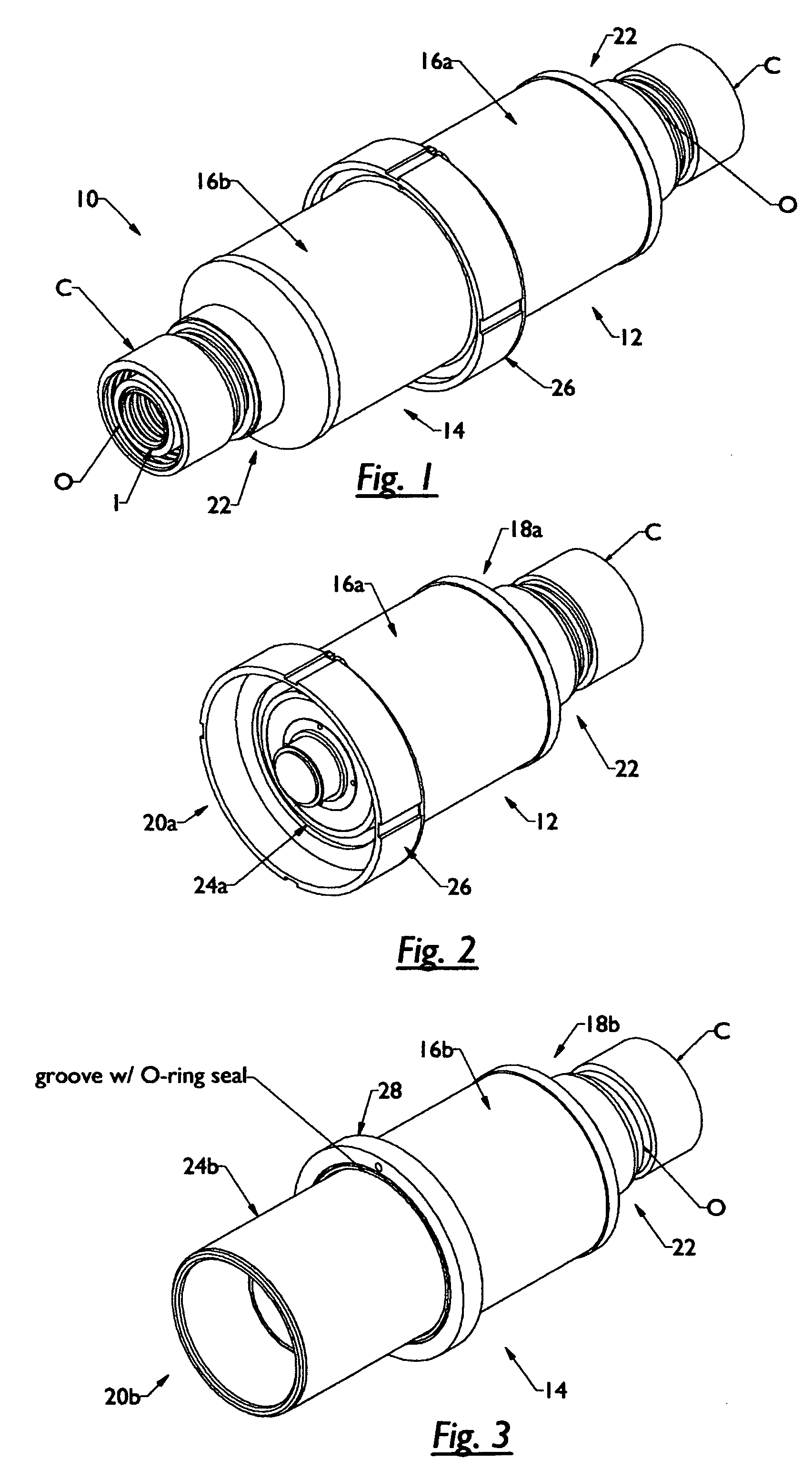
[0043]In order to provide for such a successful connection, the present invention 10, as seen in FIGS. 1-3, comprises a female termination portion 12 (FIGS. 1 and 2) and a male termination portion 14 (FIGS. 1 and 3). The female and male termination portions being adapted to be removably secured to each other. It is noted that shown is the use of female and male connecting means, but it is to be understood by those skilled in the art that other forms can be utilized when mating or connecting the termination portions.

[0044]As seen in these drawings, the female and male termination portions each include an outer shell 16a and 16b, respectively. Each shell member has opposite ends. The ends being 18a and 20a for the female termination portion and 18b and 20b for the male termination portion.

[0045]Extending outwardly from the first end 18a and 18b of each termination portion is a receiving end 22. This receiving end is structured so as to receive and mate with a conventional cryogenic co...

second embodiment

[0066]As shown in this second embodiment, in FIG. 8a, the opposite end can extend beyond the inner sleeve 46a. In essence, as seen in FIGS. 8a, 8b, and 9, the electrical conductor 62a, such as a wire, tape form, or the like is coupled to the electrical connecting element 60a. This electrical conductor 62a extends from the electrical connecting element 60a through encapsulated material 52a and to the exterior of the cryogenic guide channel 50a. This will allow for the electrical conductor of the conventional conduit, illustrated, but not labeled, to mate with the electrical connecting element 60a via the electrical conductor 62a. Such a configuration will ensure electrical communication within the female portion of the coupler of the present invention.

[0067]The male termination portion 14, for this second embodiment is shown in FIGS. 7a, 7b and 9. As with the previous embodiment, this male termination portion will mate with and receive the female termination portion 12 to provide for...

third embodiment

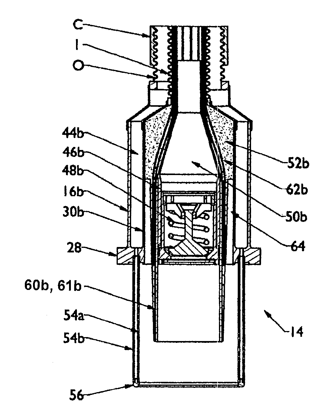
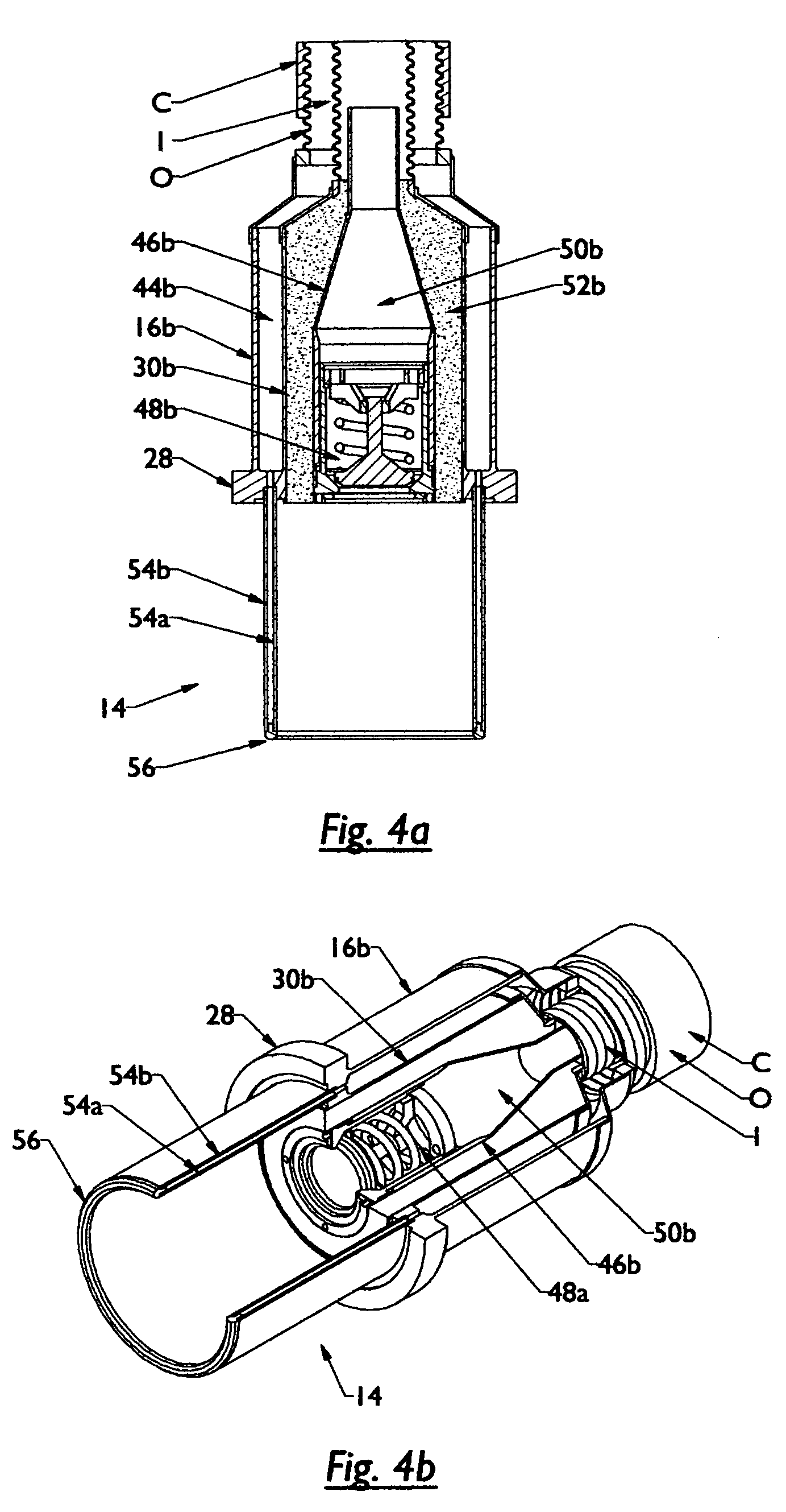
[0087]The male termination portion 14, for this third embodiment is shown in FIGS. 10a, 10b and 12. As with the previous embodiment, this male termination portion will mate with and receive the female termination portion 12 to provide for a connector that enables fluid flow as well as simultaneous electrical connection. Disconnection of the male termination portion 14 to the female termination portion will prevent fluid flow and will disconnect electrical connection.

[0088]To provide for such a configuration, the male termination portion 14 being substantially the same as the first and second embodiment, thus includes an inner shell 30b having opposite; wherein the first end being designed and configured to include several tubes or conical structures, so as to make a hermetic seal to the end of the inner jacket I of the conventional conduit C.

[0089]A locking means is utilized for locking the male portion to the female portion. Sealing collar 28 is received within the collar receiving...


PUM


Abstract

An apparatus that enables quick disconnect termination or connection for cryogenic transfer lines is presented. The apparatus is a connector that will allow two lines to be connected and coupled for simultaneously allowing for fluid to occur and electrical communication to ensue. Connection and termination will occur successfully under a pressurized environment.

Description

[0001]This is a utility application claiming priority of Provision Application No. U.S. 60 / 967,868 filed on Sep. 7, 2007.FEDERALLY SPONSORED[0002]This is a federally sponsored project, sponsored by the Office of Naval Research SBIR Contract # N00014-08-C-0163BACKGROUND OF THE INVENTION[0003]1. Field of the Invention[0004]The present invention relates generally to an apparatus designed and configured to enable quick disconnect termination or connection for cryogenic transfer lines. More particularly, the present invention will render successful mating between two lines by coupling cryogenic spaces while simultaneously enabling an electrical connection to occur therein.[0005]2. Description of the Prior Art[0006]Connectors, also known as couplers, are well known in the art and are used in a variety of fields and areas. The purpose of a connector is to mate lines in order to form a continuous route for a particular flow configuration. For example, connectors having valves therein, such ...

Claims


Application Information

Patent Timeline
Patent Type & Authority Patents(United States)
IPC IPC(8): F16L25/01H01R4/60
CPCF16L37/32F16L25/01F16L39/005Y10T403/18F16L59/141F16L59/18H01R13/005H02G15/34
Inventor MARSHALL, WILLIAM SCOTT
Owner AMERICAN SUPERCONDUCTOR
Why Eureka
Try Eureka