Focus assist through intensity control of light source

a technology of intensity control and assist, applied in the field of optical metrology, can solve the problem that the detector cannot experience total saturation during the process of finding focus, and achieve the effect of eliminating the tilt of the sampl

Active Publication Date: 2013-08-27
BRUKER NANO INC
View PDF3 Cites 5 Cited by
  • Summary
  • Abstract
  • Description
  • Claims
  • Application Information

AI Technical Summary

Benefits of technology

[0011]The concept of the invention is applicable as well in eliminating tilt in a sample being measured. Since tilt produces loss of energy in the direction of the optical path of a microscope, the irradiance received at the detector will be maximum when the sample is in a no-tilt position, i.e., perpendicular to the optical path. Therefore, according to the concept of the invention, the no-tilt position of the sample can be found by setting the initial intensity of the source to a level that causes a predetermined degree of detector saturation and then varying the intensity as necessary to maintain that degree of saturation as the tilt position of the sample is changed in the X-Y plane (that is, as the angle between the objective and the sample is varied with respect to both X and Y).

Problems solved by technology

As a result of this approach, the detector cannot experience total saturation during the process of finding focus, a recurring problem with prior-art procedures.

Method used


Image

  • Focus assist through intensity control of light source
  • Focus assist through intensity control of light source
  • Focus assist through intensity control of light source

Examples


Embodiment Construction

[0016]The term “image depth,” as used herein, is intended to refer to the range of scanner positions within which the image of the sample is visible during a vertical scan of an interferometer. The term “depth of focus” refers to the range of scanner positions within which the sample is in focus during the vertical scan of the interferometer. The term “depth of fringes” refers to the range of scanner positions within which interferometric fringes produced by the sample are visible during the vertical scan of the interferometer.

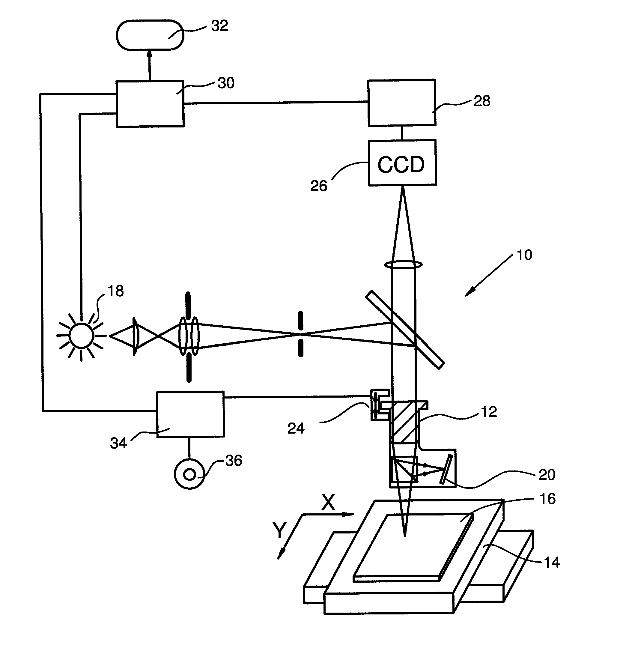
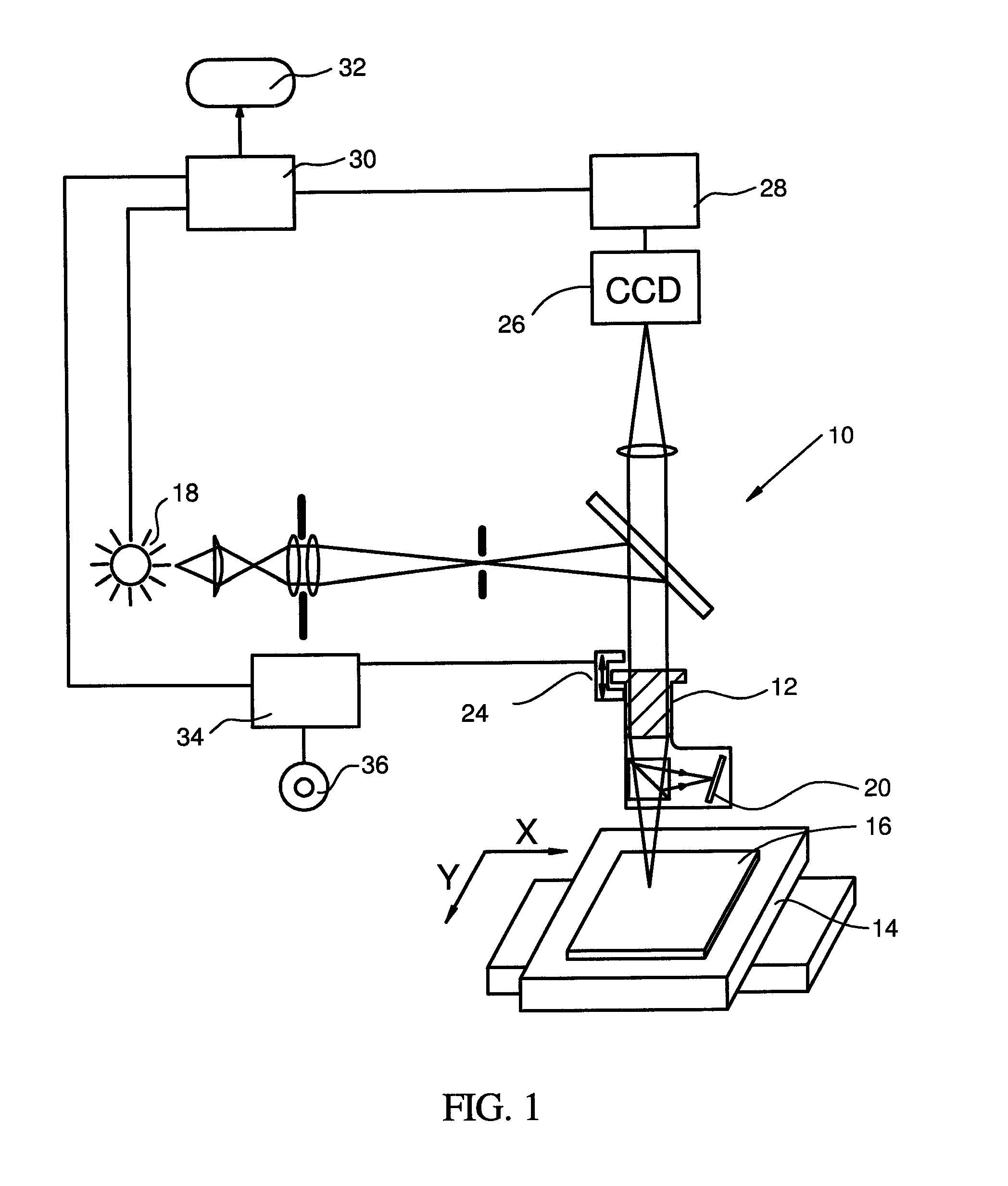
[0017]Referring to the figures, wherein like parts are referenced with the same numerals and symbols, FIG. 1 represents schematically a Z-scanning interferometer 10 with a microscope objective 12 and a sample stage 14 capable of relative translation in the X and Y plane (in a single direction, or in serpentine or raster fashion, as the need may be) to acquire images of multiple portions of a sample surface 16. As used herein, X and Y refer to the plane coordin...


PUM


Abstract

The power input to the light source of a microscope is varied as necessary to maintain a constant degree of detector saturation as the objective is moved toward a best-focus position. Focus is found by tracking the source's intensity necessary to maintain the detector irradiance at a constant level. The in-focus position is reached when the power input (and correspondingly the intensity of the light emitted by the source) reaches a minimum. The concept can be applied in a similar manner to minimize or eliminate tilt in a sample.

Description

BACKGROUND OF THE INVENTION[0001]1. Field of the Invention[0002]This invention pertains to the general field of optical metrology. In particular, it pertains to a novel method and apparatus for assisting the manual or automated process of finding best focus for an imaging optical system.[0003]2. Description of the Prior Art[0004]The process of placing a sample in optimal focal position for imaging purposes, such as for interferometric measurements, is well understood and has been implemented using a variety of approaches that are typically based on finding the position corresponding to maximum irradiance at the detector. However, the depth of focus of an imaging optical system such as an interferometric objective is often greater than the depth of fringes produced by it. Therefore, the sample may be in focus and exhibit a high level of irradiance at the detector even though interference fringes are not visible. In such situation an erroneous measurement or no measurement at all may ...

Claims


Application Information

Patent Timeline
Patent Type & Authority Patents(United States)
IPC IPC(8): G02B7/09
CPCG01B11/26G02B7/38G02B21/244
Inventor FARRELL, COLIN
Owner BRUKER NANO INC
Why Eureka
Try Eureka