
Dryer for fuel material

a fuel material and dryer technology, applied in the field of dryers, can solve the problems of a large moisture content of products, a large loss of heat energy generated during their consumption, and a non-uniform burning of products, and achieve the effect of reducing the number of burners

Active Publication Date: 2013-09-03
ALTENTECH POWER
View PDF40 Cites 4 Cited by
  • Summary
  • Abstract
  • Description
  • Claims
  • Application Information

AI Technical Summary

Benefits of technology

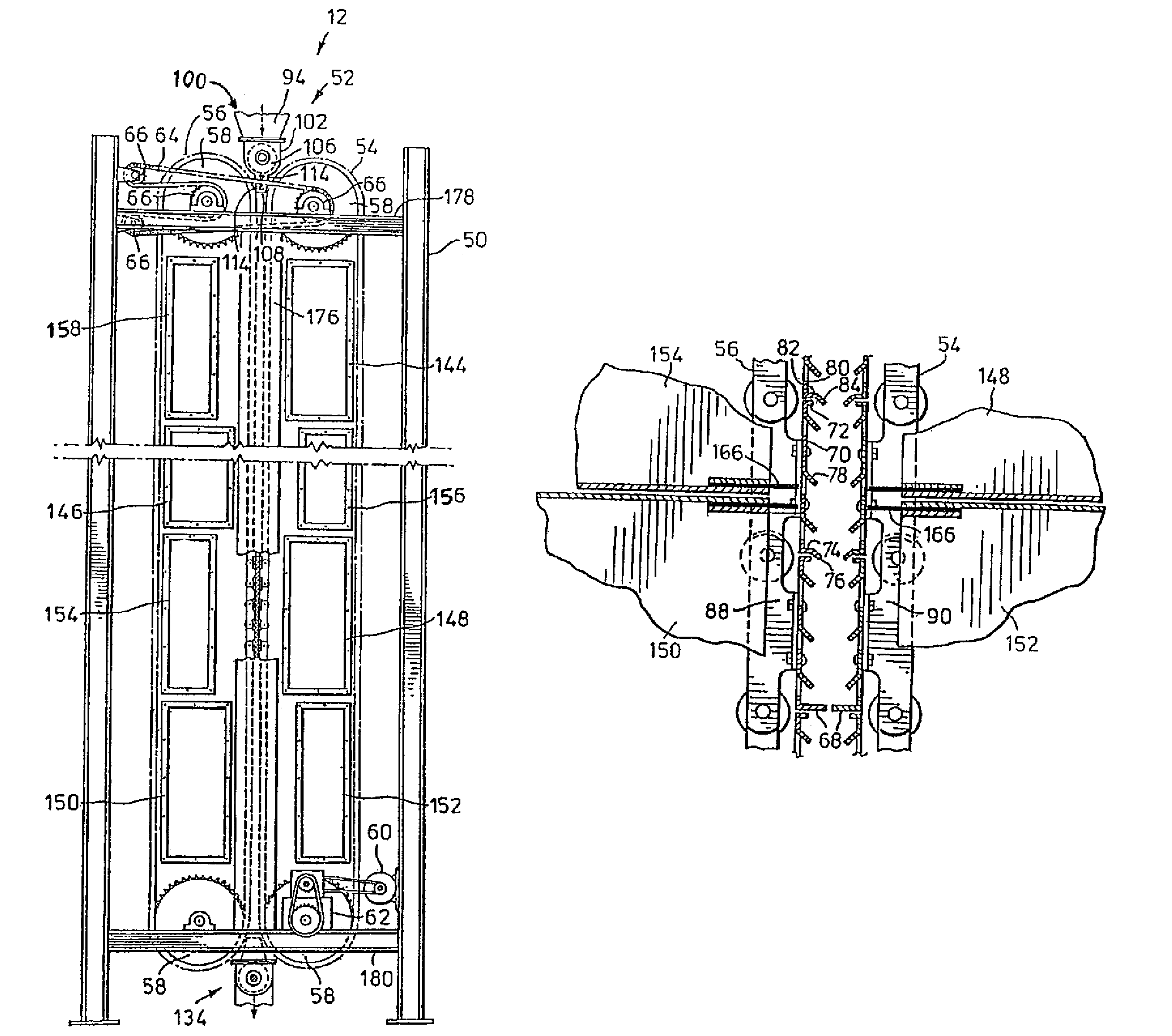
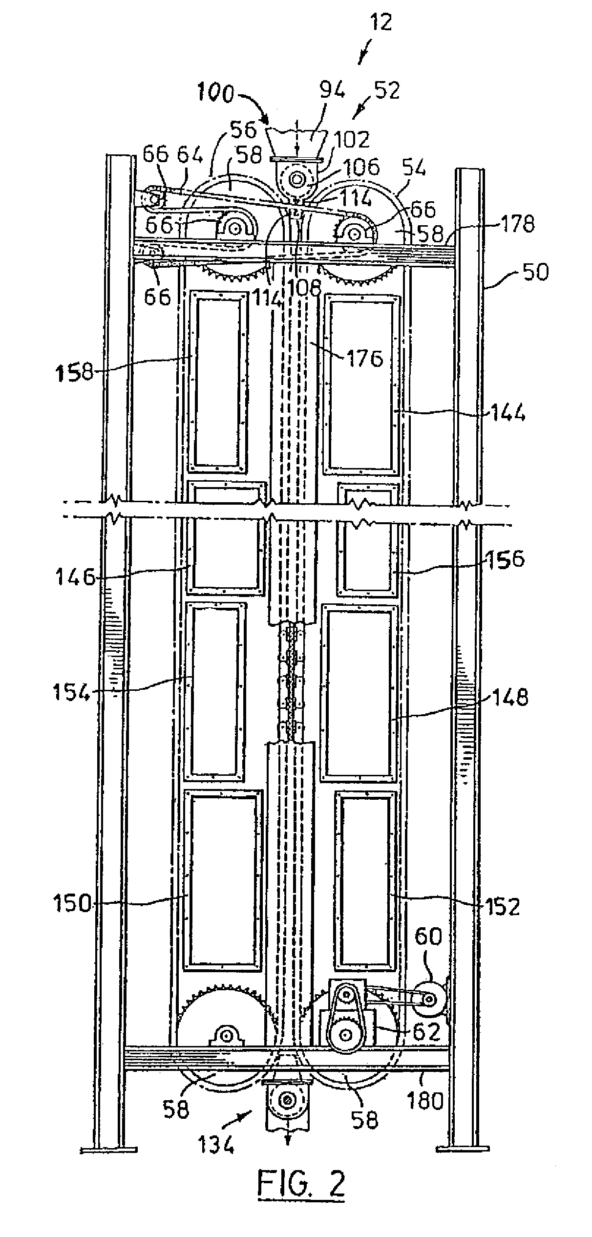
This patent describes two types of dryers used for removing moisture from fuel material. The first dryer uses a vertical conveyor and a heated gas to remove moisture from the material as it moves through the dryer. The second dryer uses a drying gas and an endless belt to move the material along a vertical path. The invention provides more efficient and effective ways of drying fuel materials, which can improve their quality and consistency.

Problems solved by technology

Such products tend to have considerable moisture content because they are often stored in locations where they are exposed to the elements.
When these products are used as a fuel in a burner, a substantial part of the heat energy generated during their consumption tends to be lost to a burner stack, as the moisture contained in the product is evaporated and escapes.
This manner of drying tends to separate fine and course materials thereby providing a dried product having non-uniform burning properties.
This separation of fine materials from coarse tends also to contribute to dust problems, fine particles tending to be entrained with drying air or otherwise scattered from the dryer.

Method used


Image

  • Dryer for fuel material
  • Dryer for fuel material
  • Dryer for fuel material

Examples


Embodiment Construction

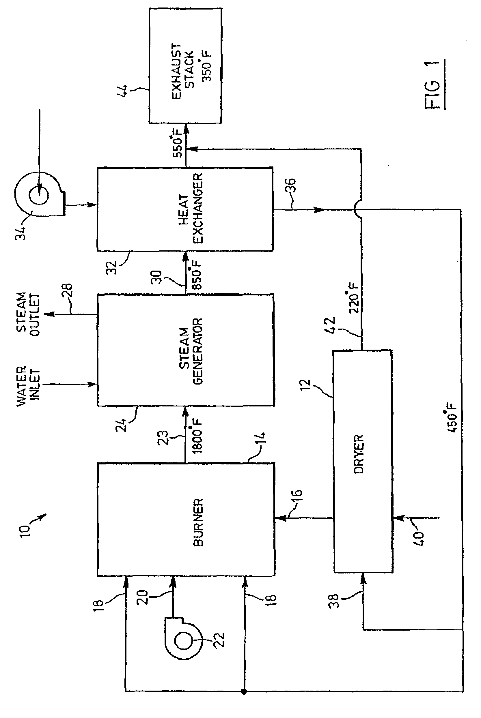
[0015]Reference is made to FIG. 1 which illustrates a steam generating system 10 including a dryer 12 constructed according to a preferred embodiment of the invention. Temperatures indicated on or adjacent to components of the steam generating system 10 are temperatures of intake or output air flows, as the case may be. It will be understood by those skilled in the art that the temperatures of intake and output air flows are intended to be exemplary of the typical system and may be varied in any suitable fashion for particular applications.

[0016]The steam generating system 10 includes a solid fuel burner 14 which receives peat moss, wood bark or other similar product at a fuel inlet 16, and air for combustion at air inlets 18 and air inlet 20 which is coupled to an air pump 22. The solid fuel burner 14 has a burner outlet 23 from which air heated to a temperature of about 1,800 degrees Fahrenheit is released.

[0017]The heated air generated at the burner outlet 23 is received by a ste...


PUM


Abstract

The invention relates to a dryer for drying fuel materials such as wood bark, wood chips, sludge, garbage, peat moss or the like. In a preferred embodiment the dryer comprises a conveyor, consisting of twin endless belts, which carries the material to be dried along a vertical path defined between parallel runs of the endless belts, and ductwork which serves to direct heated air (received from any appropriate source) across the vertical path to remove moisture from the material as it is being conveyed. The ductwork includes at least one feed duct for use in delivering the heated air to one side of the vertical path, and at least one exhaust duct for use in withdrawing moisture-laden air on another side of the vertical path. Suction is applied at the exhaust ducts to draw drying air through the ductwork, and the feed and exhaust ducts are made to seal against the conveyor to reduce the introduction of ambient air into the dryer ductwork under the suction applied.

Description

FIELD OF THE INVENTION[0001]The invention relates to a dryer for use in drying fuel materials such as wood bark, wood chips, sludge, peat moss or the like.BACKGROUND OF THE INVENTION[0002]Dryers may be used to remove moisture from a variety of fuel materials. One example of such fuel materials are peat moss or peat moss pellets that are intended to be burned as a fuel. Such products tend to have considerable moisture content because they are often stored in locations where they are exposed to the elements. When these products are used as a fuel in a burner, a substantial part of the heat energy generated during their consumption tends to be lost to a burner stack, as the moisture contained in the product is evaporated and escapes. Fuel economy can be enhanced by reducing the moisture content of these products prior to combustion.[0003]Drying apparatuses have been used in which wood by-products have been tumbled in a rotating fashion while being subjected to drying air. This manner o...

Claims


Application Information

Patent Timeline
Patent Type & Authority Patents(United States)
IPC IPC(8): F26B13/02
CPCF26B17/026F26B17/06F26B23/028F26B25/003F26B2200/18F26B2200/24F26B2200/04
Inventor TUCK, GORDON
Owner ALTENTECH POWER
Learn More