Multiple-row large roller bearing, especially axial radial bearing for the main arrangement of bearings of the rotor shaft of a wind power installation

a technology of axial radial bearings and roller bearings, which is applied in the direction of bearing units, rigid supports, machines/engines, etc., can solve the problems of relatively high friction moment, unfavorable kinematics, and the design of rolling bodies as bearing needles or cylinder rollers, etc., to achieve favorable kinematics, facilitate assembly and disassembly, and high degree of axial tilting resistance

Inactive Publication Date: 2013-09-03
SCHAEFFLER TECH AG & CO KG
View PDF25 Cites 20 Cited by
  • Summary
  • Abstract
  • Description
  • Claims
  • Application Information

AI Technical Summary

Benefits of technology

[0011]The invention is therefore based on the realization that, by exchanging the rolling bodies for the two rolling bearings for absorbing axial forces, which rolling bodies have hitherto been designed as cylindrical rollers or bearing needles, for rolling bodies designed as tapered rollers or bearing balls, it is possible in a simple manner to improve the kinematics of said rolling bearings while maintaining the same load capacity, in such a way that the rolling bodies roll on their raceways with the same rotational speeds on all their circumferential surfaces, such that skew or permanent tilting movements of the rolling bodies in their cage pockets, and the associated friction losses together with the increased generation of heat in the bearing, are now eliminated.
[0013]According to another embodiment, it is provided in the large rolling bearing designed according to the invention that, with the two rolling bearings for absorbing axial forces designed as tapered-roller bearings, each row of the rolling bodies, which are designed as tapered rollers, rolls in one raceway each which is delimited by at least one rim and which is formed entirely either into the inner sides of the shaft disks or into the outer sides of the outer disk. In this way, one part of the raceways is of planar design and therefore permits the adjustment of the radial preload both of the rolling body rows of the rolling bearing for absorbing radial forces and also of the two rolling body rows of the rolling bearings for absorbing axial forces, without constraining forces or elastic deformations. Here, the at least one rim, which delimits each raceway, is operatively connected, in each case, to the larger end sides of the tapered rollers, and has the advantage that the guidance of the tapered rollers in their raceways is provided no longer by means of the bearing cage, but rather by means of said rim, and the bearing cage has merely the function of a spacer with which the tapered rollers are held at uniform intervals to one another in the circumferential direction.
[0016]An expedient refinement, which applies to all three of the above-described embodiments, of the large rolling bearing designed according to the invention, is furthermore, that the inner ring and the shaft disks are formed either by separate individual parts or the inner ring is formed in one piece with the one shaft disk and the other shaft disk forms a separate component. Here, the design of the inner ring and shaft disks as separate components has proven to be advantageous with regard to the production costs of the individual parts and also with regard to easier assembly and disassembly of the axial-radial bearings, while the single-part design of the inner ring with one of the shaft disks has advantages with regard to the axial dimensional accuracy of the axial-radial bearing as a result of the shorter tolerance chain, and with regard to a particularly high degree of axial tilting resistance. Also conceivable in this connection, however, would be a design of the axial-radial bearing in which one half of the inner ring including one half of the raceway for the cylindrical rollers of the rolling bearing for absorbing radial forces is integrated into the one shaft disk, while the other half of the inner ring and the other half of the raceway are formed in one piece with the other shaft disk. In the case of the separate design of the inner ring and shaft disks, the most advantageous option for connecting the individual parts to one another has proven to be a plurality of uniformly circumferentially distributed screw connections, while in case of the single-part design of the inner ring with one of the shaft disks, the most suitable option is a non-positively locking connection of all the individual parts by means of clamping rings which, by means of a press-fitting connection with the mounted shaft, brace the one shaft disk against the inner ring which is combined with the other shaft disk.
[0017]Finally, it is also proposed, as an advantageous refinement of all the embodiments of the large rolling bearing designed according to the invention, that, to set the axial play of the rolling bearings for absorbing axial forces which are designed as tapered-roller bearings, angular-contact ball bearings or axial ball bearings, either the inner ring is formed with a defined width by means of grinding of at least one of its axial sides, or a spacer ring with a defined width is arranged between the inner ring and at least one of the shaft disks. As an alternative to the grinding of one of the axial sides of the inner ring to a defined width fo setting the axial play, it is also possible, however, to perform corresponding cutting by machining on both axial sides of the inner ring or else on both inner sides of the shaft disks, or to influence the axial dimension of said inner ring or shaft disks by means of coatings. However, since such machining is relatively complex and expensive in production terms, setting the axial play by means of a spacer ring has proven to be the most advantageous option both for cost reasons and also because, any machining errors in the width of the spacer ring can also be compensated in a relatively simple manner by exchanging for a suitable spacer ring in this way.
[0018]In summary, the axial-radial bearing designed according to the invention, in all the described embodiments, has the advantage over the axial-radial bearings known from the prior art that the rolling bodies, which are designed as tapered rollers or as bearing balls, of the two rolling bearings for absorbing axial forces, have more favorable kinematics than the cylindrical rollers or bearing needles used previously, and have rim guidance instead of cage guidance, such that permanent tilting movements of the rolling bodies in their cage pockets, with friction losses and increased heat generation in the bearing and high constraining forces on the bearing cages thereof, are effectively avoided and the service life of the axial-radial bearing is extended significantly. Since, as a rolling bearing for absorbing radial forces, use is made as before of a single-row, solid-roller cylindrical roller bearing or cylindrical roller bearing formed with a bearing cage, the axial-radial bearing is simultaneously also suitable for very high loads.

Problems solved by technology

A disadvantage of said axial-radial bearings has however proven to be that the rolling bodies designed as bearing needles or cylinder rollers, in the two rolling bearings for absorbing axial forces have unfavorable kinematics, since said rolling bodies are arranged with their end sides on different pitch circles on account of their axial arrangement, and thereby seek to roll at different rotational speeds on their raceways at said end sides.
However, since this is naturally not possible and the rolling bodies are also guided only by their bearing cages, skew or permanent tilting movements of the bearing needles or cylindrical rollers in their cage pockets occurs, as a result of which tilting movements, high constraining forces act on the bearing cages, and which tilting movements cause a relatively high friction moment and an increased generation of heat in the bearing.
Here, the generation of heat in the bearing and / or the constraining forces on the bearing cages may briefly become so high as to result in either overheating and inadequate lubrication or in breakage of the bearing cages as a result of overloading, which in both cases leads to premature failure of the axial-radial bearing.
Such unfavorable kinematics may duly be eliminated by using the described axial-angular-contact ball bearings with bearing balls, which naturally have more expedient kinematics, instead of the likewise described axial-radial bearings with cylindrical rollers, but such axial-angular-contact ball bearings generally do not have the required load capacity to be able to withstand extremely high forces prevailing, for example, in the main bearing arrangement of a rotor shaft of a wind power installation.

Method used


Image

  • Multiple-row large roller bearing, especially axial radial bearing for the main arrangement of bearings of the rotor shaft of a wind power installation
  • Multiple-row large roller bearing, especially axial radial bearing for the main arrangement of bearings of the rotor shaft of a wind power installation
  • Multiple-row large roller bearing, especially axial radial bearing for the main arrangement of bearings of the rotor shaft of a wind power installation

Examples


first embodiment

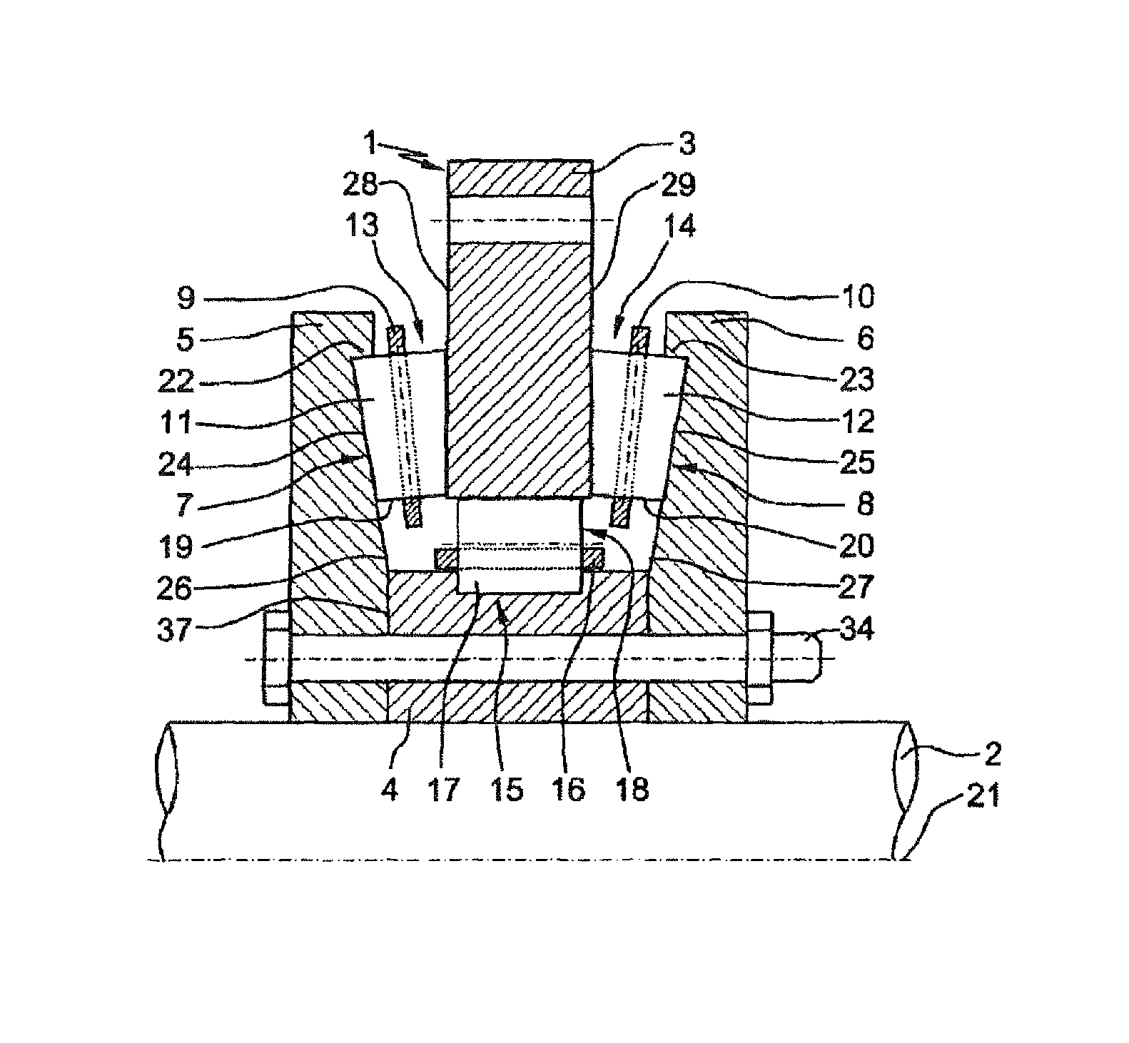
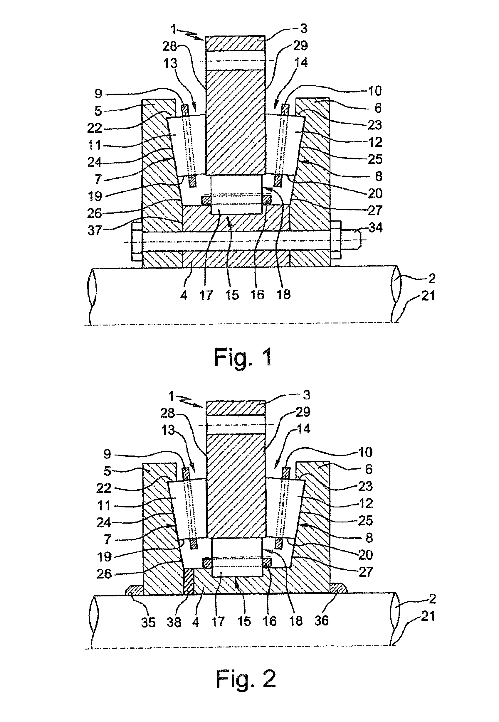
[0022]FIG. 1 shows a partial view of a cross section through a multi-row large rolling bearing designed according to the invention;

[0023]FIG. 2 shows a partial view of a cross section through a variant of the first embodiment of a multi-row large rolling bearing designed according to the invention;

second embodiment

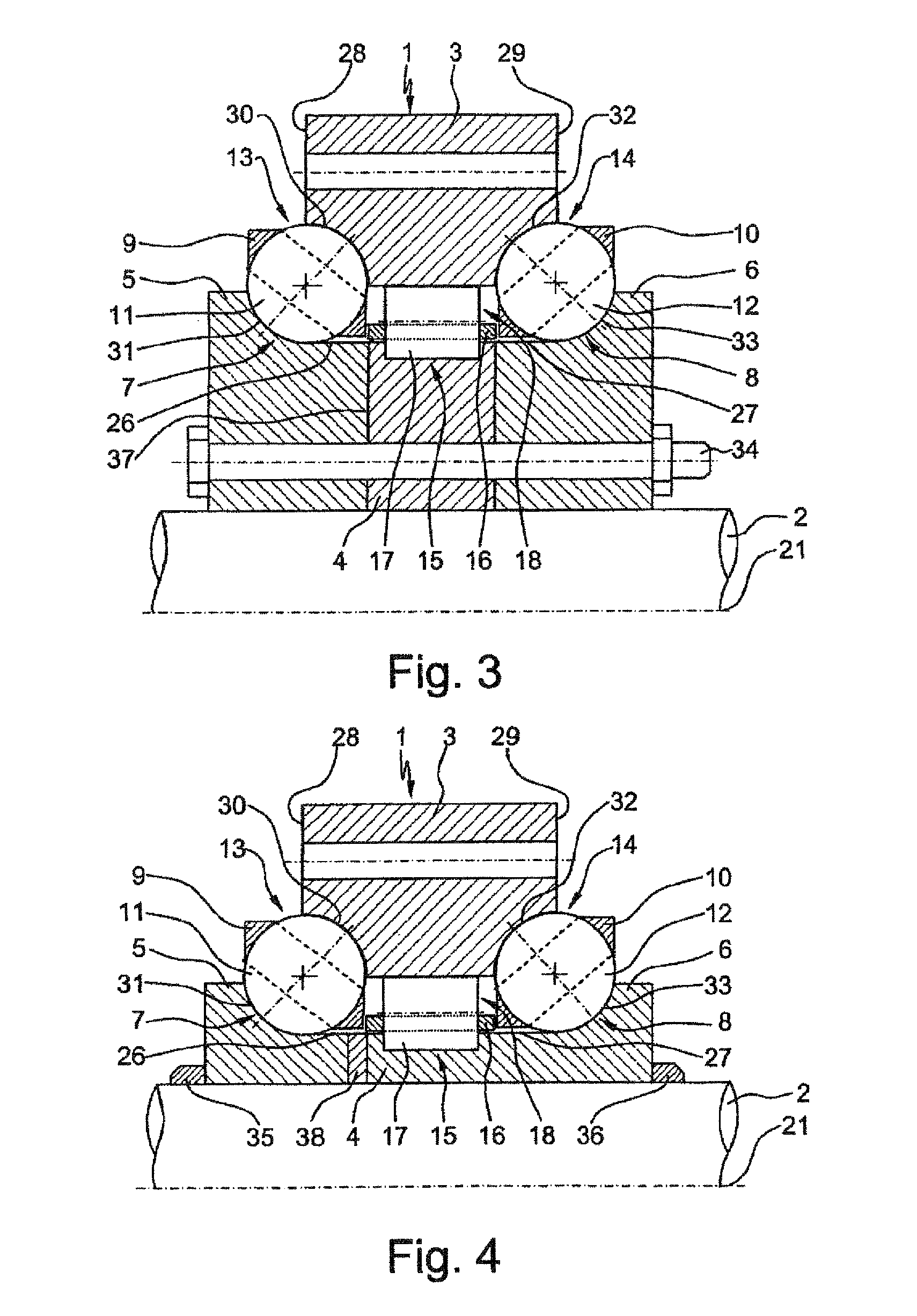
[0024]FIG. 3 shows a partial view of a cross section through a multi-row large rolling bearing designed according to the invention;

[0025]FIG. 4 shows a partial view of a cross section through a variant of the second embodiment of a multi-row large rolling bearing designed according to the invention;

third embodiment

[0026]FIG. 5 shows a partial view of a cross section through a multi-row large rolling bearing designed according to the invention; and

[0027]FIG. 6 shows a partial view of a cross section through a variant of the third embodiment of a multi-row large rolling bearing designed according to the invention.


PUM

PropertyMeasurementUnit
axial forcesaaaaaaaaaa
radial forcesaaaaaaaaaa
widthaaaaaaaaaa

Abstract

An axial radial bearing for a rotor shaft of a wind power installation, which has a vertical circular outer disk, inner ring arranged coaxially to the outer disk, and two circular shaft washers axially arranged on both sides of the outer disk. At least one row of rolling bodies, held at equal distances by a bearing cage, extends between the shaft washers and outer disk, forming the rolling bearings for receiving axial forces, while at least one other row of rolling bodies, optionally held at equal distances by another bearing cage, is arranged between the outer disk and inner ring, forming a third rolling bearing for receiving radial forces. The two rolling bearings for receiving radial forces are formed by two tapered roller bearings oriented towards the longitudinal axis of the bearing by the small front sides, or by a double-row angular ball bearing or by two axial ball bearings.

Description

CROSS REFERENCE TO RELATED APPLICATIONS[0001]This application is a 371 of PCT / EP2008 / 010374 filed Dec. 8, 2008, which in turn claims the priority of DE 10 2007 063 160.1 filed Dec. 29, 2007, the priority of both applications is hereby claimed and both applications are incorporated by reference herein.FIELD OF THE INVENTION[0002]The invention relates to a multi-row large rolling bearing according to the features forming the preamble of patent claim 1, and may particularly advantageously be realized in an axial-radial bearing for the main bearing arrangement of the rotor shaft of a wind power installation or in rotary table bearings or rotary joints.BACKGROUND OF THE INVENTION[0003]Large rolling bearings which are suitable for the main bearing arrangement of the rotor shaft of a wind power installation, or else for rotary table bearing arrangements in machine tools, are usually produced as ready-to-install bearing units for combined loadings with high demands on running precision, and...

Claims


Application Information

Patent Timeline
Patent Type & Authority Patents(United States)
IPC IPC(8): F16C19/54F16C33/58F16C35/08F16C19/32
CPCF03D11/0008F16C19/49F16C19/381F16C33/60F16C2300/14F16C2226/60Y02E10/722F16C2229/00F16C2322/39F03D80/70F16C2360/31Y02E10/72
Inventor LOESCHNER, TIMZEIDLHACK, RUDOLF
Owner SCHAEFFLER TECH AG & CO KG
Why Eureka
Try Eureka