Laser-driven light source

a laser-driven light source and laser-driven technology, which is applied in the direction of optical radiation measurement, x-ray tubes, gas-filled discharge tubes, etc., can solve the problems of insufficient brightness of arc lamps in some applications, unstable position of arc lamps, and failure of light sources, so as to reduce the noise of light sources

Active Publication Date: 2013-09-03
HAMAMATSU PHOTONICS KK
View PDF30 Cites 60 Cited by
  • Summary
  • Abstract
  • Description
  • Claims
  • Application Information

AI Technical Summary

Benefits of technology

[0019]In some embodiments, the at least one laser is a continuous wave laser or a high pulse rate laser. In some embodiments, the at least one laser is a high pulse rate laser that provides pulses of energy to the ionized medium so the high brightness light is substantially continuous. In some embodiments, the magnitude of the high brightness light does not vary by more than about 90% during operation. In some embodiments, the at least one laser provides energy substantially continuously to minimize cooling of the ionized medium when energy is not provided to the ionized medium.
[0090]The invention, in another aspect, relates to a method for decreasing noise of a light source within a predetermined frequency band. The light source includes a laser diode. A current of the laser diode is modulated at a frequency greater than the predetermined frequency band causing the laser to rapidly switch between different sets of modes to decrease noise of the light source within the predetermined frequency band.

Problems solved by technology

As a result, the anode and / or cathode are prone to wear and may emit particles that can contaminate the light source or result in failure of the light source.
Also, these arc lamps do not provide sufficient brightness for some applications, especially in the ultraviolet spectrum.
Further, the position of the arc can be unstable in these lamps.

Method used


Image

  • Laser-driven light source
  • Laser-driven light source
  • Laser-driven light source

Examples


Embodiment Construction

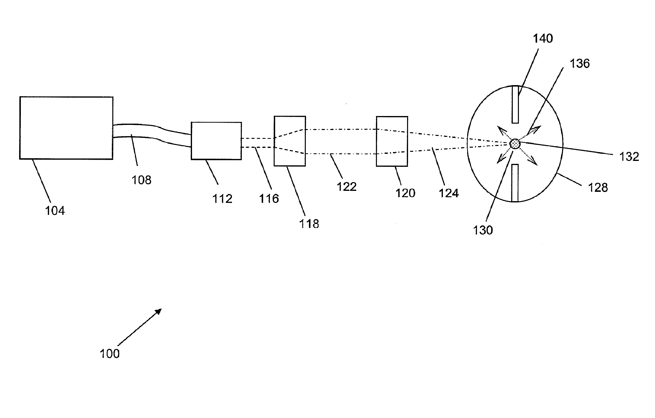
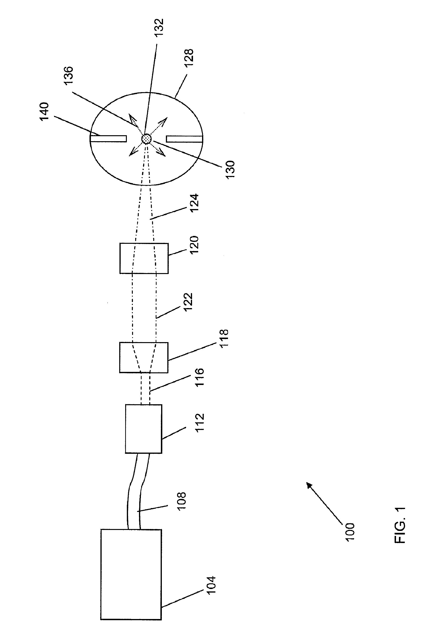
[0135]FIG. 1 is a schematic block diagram of a light source 100 for generating light that embodies the invention. The light source 100 includes a chamber 128 that contains an ionizable medium (not shown). The light source 100 provides energy to a region 130 of the chamber 128 having the ionizable medium which creates a plasma 132. The plasma 132 generates and emits a high brightness light 136 that originates from the plasma 132. The light source 100 also includes at least one laser source 104 that generates a laser beam that is provided to the plasma 132 located in the chamber 128 to initiate and / or sustain the high brightness light 136.

[0136]In some embodiments, it is desirable for at least one wavelength of electromagnetic energy generated by the laser source 104 to be strongly absorbed by the ionizable medium in order to maximize the efficiency of the transfer of energy from the laser source 104 to the ionizable medium.

[0137]In some embodiments, it is desirable for the plasma 132...


PUM

PropertyMeasurementUnit
wavelengthaaaaaaaaaa
poweraaaaaaaaaa
poweraaaaaaaaaa

Abstract

An apparatus for producing light includes a chamber and an ignition source that ionizes a gas within the chamber. The apparatus also includes at least one laser that provides energy to the ionized gas within the chamber to produce a high brightness light. The laser can provide a substantially continuous amount of energy to the ionized gas to generate a substantially continuous high brightness light.

Description

RELATED APPLICATIONS[0001]This application is a continuation-in-part of U.S. Ser. No. 12 / 166,918, filed on Jul. 2, 2008, which is a continuation-in-part of U.S. Ser. No. 11 / 695,348, filed on Apr. 2, 2007, which is a continuation-in-part of U.S. Ser. No. 11 / 395,523, filed on Mar. 31, 2006, the entire disclosures of which are incorporated by reference herein. This application claims the benefit of, and priority to U.S. Provisional Patent Application No. 61 / 302,797, filed on Feb. 9, 2010, the entire disclosure of which is incorporated by reference herein.FIELD OF THE INVENTION[0002]The invention relates to methods and apparatus for providing a laser-driven light source.BACKGROUND OF THE INVENTION[0003]High brightness light sources can be used in a variety of applications. For example, a high brightness light source can be used for inspection, testing or measuring properties associated with semiconductor wafers or materials used in the fabrication of wafers (e.g., reticles and photomask...

Claims


Application Information

Patent Timeline
Patent Type & Authority Patents(United States)
IPC IPC(8): G01J1/00
CPCB82Y10/00G03F7/70033H01J61/16H01J65/04H05B41/382H05G2/003H05G2/008G21K5/00G21K5/04H05G2/001Y10T29/49002Y02B20/204H05G2/005Y02B20/00G01J1/4257H01J65/042
Inventor SMITH, DONALD K.BESEN, MATTHEWZHU, HUILINGSTOLYAROV, DANIILYE, HONGKEHILL, GORDONCOLLINS, RON
Owner HAMAMATSU PHOTONICS KK
Why Eureka
Try Eureka