
High-side signal sensing circuit

a signal sensing circuit and high-side technology, applied in the field of signal sensing circuits, can solve the problems of low accuracy, difficult control of illumination, and resistors used as voltage dividers for high-side signal sensing, and achieve the effect of easy access to current flowing through output resistors

Active Publication Date: 2013-09-03
SEMICON COMPONENTS IND LLC
View PDF10 Cites 0 Cited by
  • Summary
  • Abstract
  • Description
  • Claims
  • Application Information

AI Technical Summary

Benefits of technology

The invention is a circuit that allows for precise sensing of high-side signals. This circuit can be used in various applications such as battery management, cell balance, LED backlight drivers, and power converters. It can be designed in a single integrated circuit and allows for easy sensing of current by measuring the voltage across a resistor.

Problems solved by technology

However, if the LOAD 170 is LEDs, the amount of current transmitted to the LOAD 170 would affect the illumination of LEDs; this means that the resistance value of resistors 120-150 would affect the illumination of LEDs when the voltage value of VH was adjusted, that is, the drawback of traditional approach, having resistors used as voltage divider for high-side signal sensing, is poor accuracy because of the temperature and process variation such that it is hard to control the illumination of LEDs and sense the load current ILOAD when the voltage value of VH was adjusted.

Method used


Image

  • High-side signal sensing circuit
  • High-side signal sensing circuit
  • High-side signal sensing circuit

Examples


Embodiment Construction

[0015]The following description is of the best-contemplated mode of carrying out the invention. This description is made for the purpose of illustrating the general principles of the invention and should not be taken in a limiting sense. The scope of the invention is best determined by reference to the appended claims.

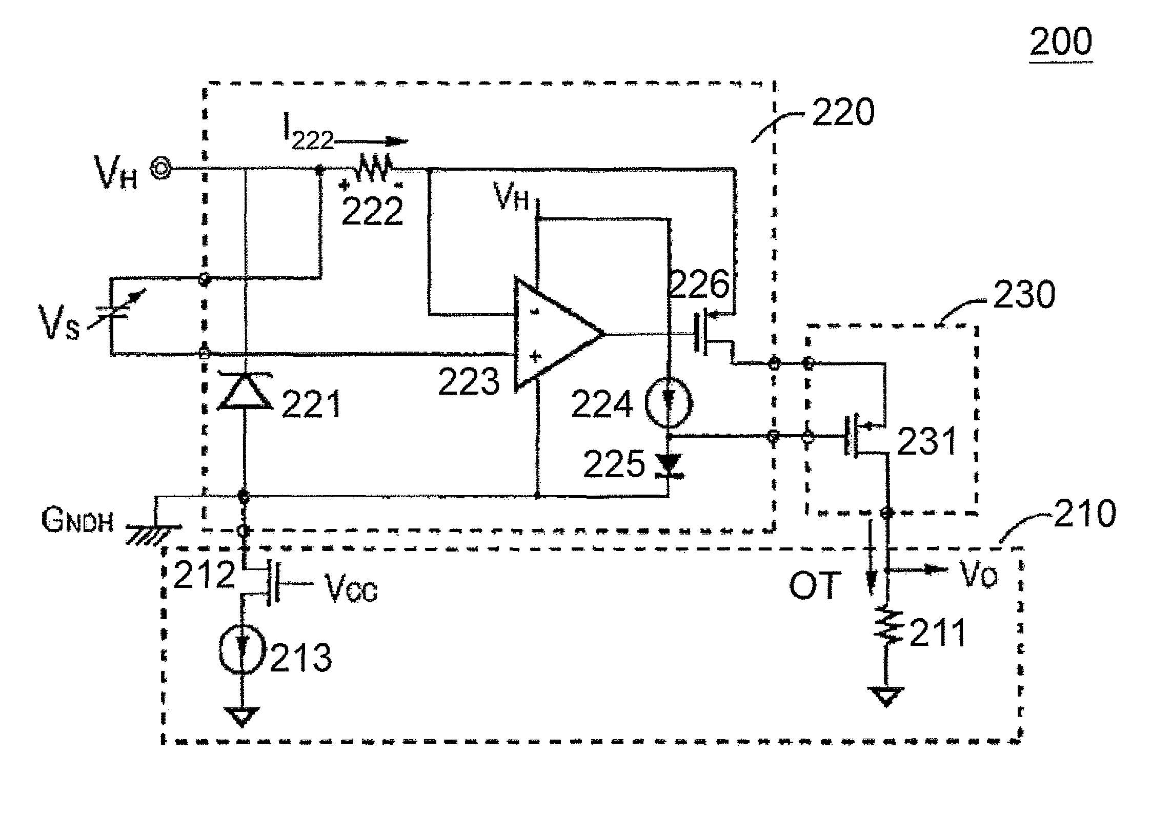
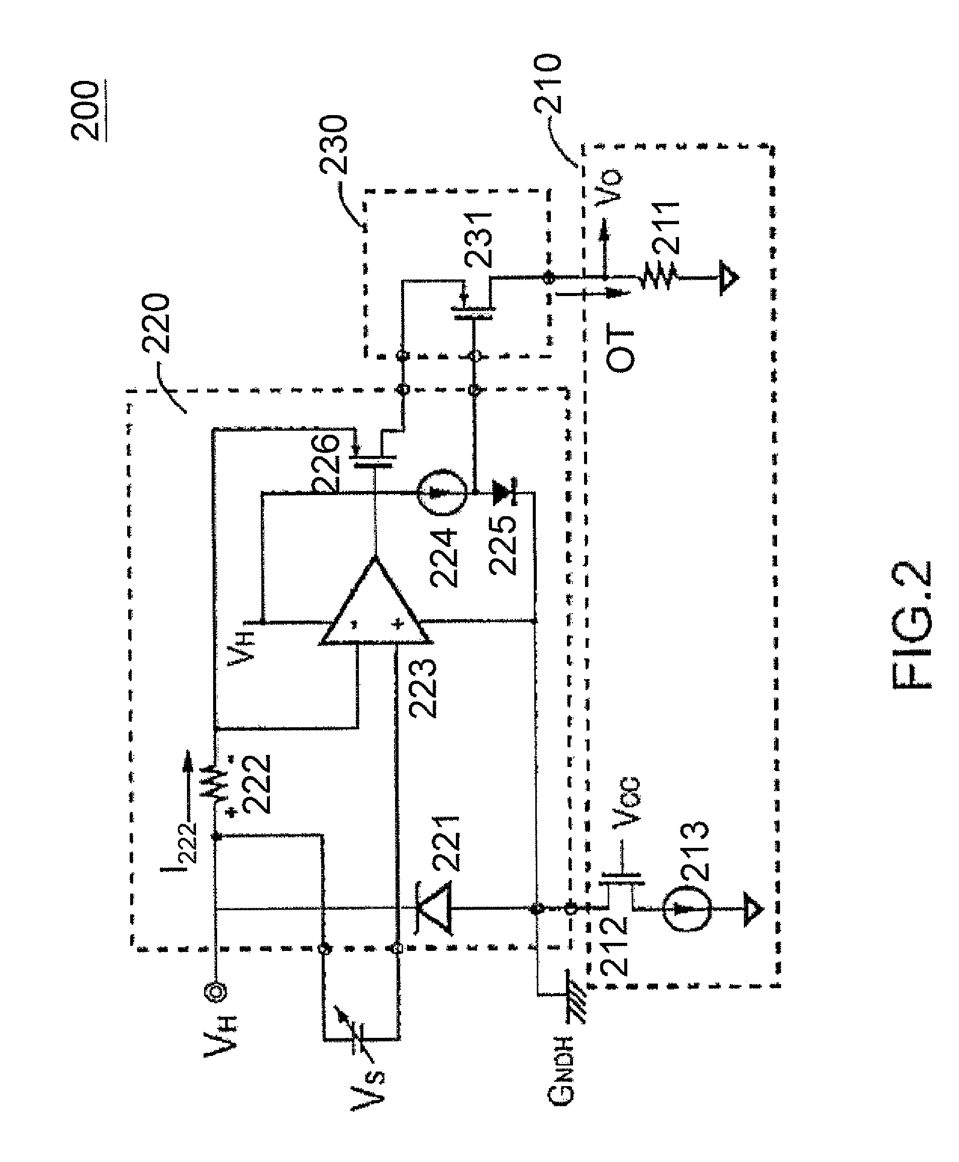
[0016]FIG. 2 shows an embodiment of a high-side signal sensing circuit 200 according to the present invention. The high-side signal sensing circuit 200 comprises a first circuit 210, second circuit 220 and third circuit 230. The first circuit 210 includes an output resistor 211 and output terminal OT, in one embodiment the first circuit 210 further includes third transistor 212 and first current source 213. The second circuit 220, such as a signal-to-current converter 220, includes a zener diode 221, first resistor 222, operational amplifier 223, second current source 224, diode 225 and first transistor 226. The third circuit 230 includes a second transistor 231.

[0017]...


PUM


Abstract

The present invention provides a high-side signal sensing circuit. The high-side signal sensing circuit comprises a signal-to-current converter, a second transistor and a resistor. The signal-to-current converter has a first transistor generating a mirror current in response to an input signal. The second transistor cascaded with the first transistor is coupled to receive the mirror current. The resistor generates an output signal in response to the mirror current. Wherein, the level of the output signal is corrected to the level of the input signal.

Description

CROSS REFERENCE TO RELATED APPLICATIONS[0001]This application claims the benefit of U.S. Provisional Application No. 61 / 491,364, filed on May 31, 2011, the contents of which are incorporated herein by reference.BACKGROUND OF THE INVENTION[0002]1. Field of the Invention[0003]The present invention relates to signal sensing circuit, and more specifically to a high-side signal sensing circuit.[0004]2. Description of the Related Art[0005]FIG. 1 shows a high-side signal sensing circuit 100 in conventional arts. The high-side signal sensing circuit 100 basically comprises an operational amplifier 110, resistors 120-160, and a LOAD 170. The voltage VH supplies power to the node between the resistor 120 and the resistor 140 such that current I140 flows through the resistor 140. Since the resistor 140 couples to the LOAD 170 and the negative input of operational amplifier 110 via the resistor 150, the current I140 would be divided into two currents, current I150 flowed through the resistor 15...

Claims


Application Information

Patent Timeline
Patent Type & Authority Patents(United States)
IPC IPC(8): G01R19/00
CPCG01R19/0092
Inventor YANG, TA-YUNGWEI, KAI-FANGCHEN, YEN-TING
Owner SEMICON COMPONENTS IND LLC
Learn More