Information processing device, method and program

a technology of information processing and information processing method, applied in the field of information processing method and information processing program, can solve the problems of large increase in delay time, expansion of loss range, and insufficient improvement of burst packet recovery performance in the fec method, so as to suppress the increase in unnecessary delay

Active Publication Date: 2013-09-03
SONY CORP
View PDF1 Cites 1 Cited by
  • Summary
  • Abstract
  • Description
  • Claims
  • Application Information

AI Technical Summary

Benefits of technology

[0014]However, as described above, even if more or less data loss occurs, merely quality for the lost part is lowered, and thus the reception side can reproduce the data using only packets which arrive in expected time. Particularly, in the case of the encoding method used in the data transmission in which a short delay is demanded, generally, since the encoding process unit becomes small, a range which is directly influenced (image quality is deteriorated) by the data loss is reduced.
[0017]Thus, it is desirable to suppress increase in unnecessary delay and to suppress error propagation to subsequent data.
[0030]The first redundancy setting means may decrease redundancy for a block which is temporally later inside the second data unit.
[0044]According to the embodiments of the present invention, it is possible to perform data transmission. Particularly, it is possible to transmit data by suppressing increase in unnecessary delay and error propagation to subsequent data.

Problems solved by technology

Therefore, if a large FEC block size is selected, there is a problem in that the delay time is greatly increased.
In other words, there is a problem in that the recovery performance for the burst packet loss is not sufficiently improved in the FEC method, in data transmission in which a short delay is demanded.
In the case of the encoding method, if irrecoverable data loss occurs, the error is propagated to subsequent data, and thus there is a problem in that a range influenced by the loss is expanded.

Method used


Image

  • Information processing device, method and program
  • Information processing device, method and program
  • Information processing device, method and program

Examples


first embodiment

1. First Embodiment

[Configuration of Network System]

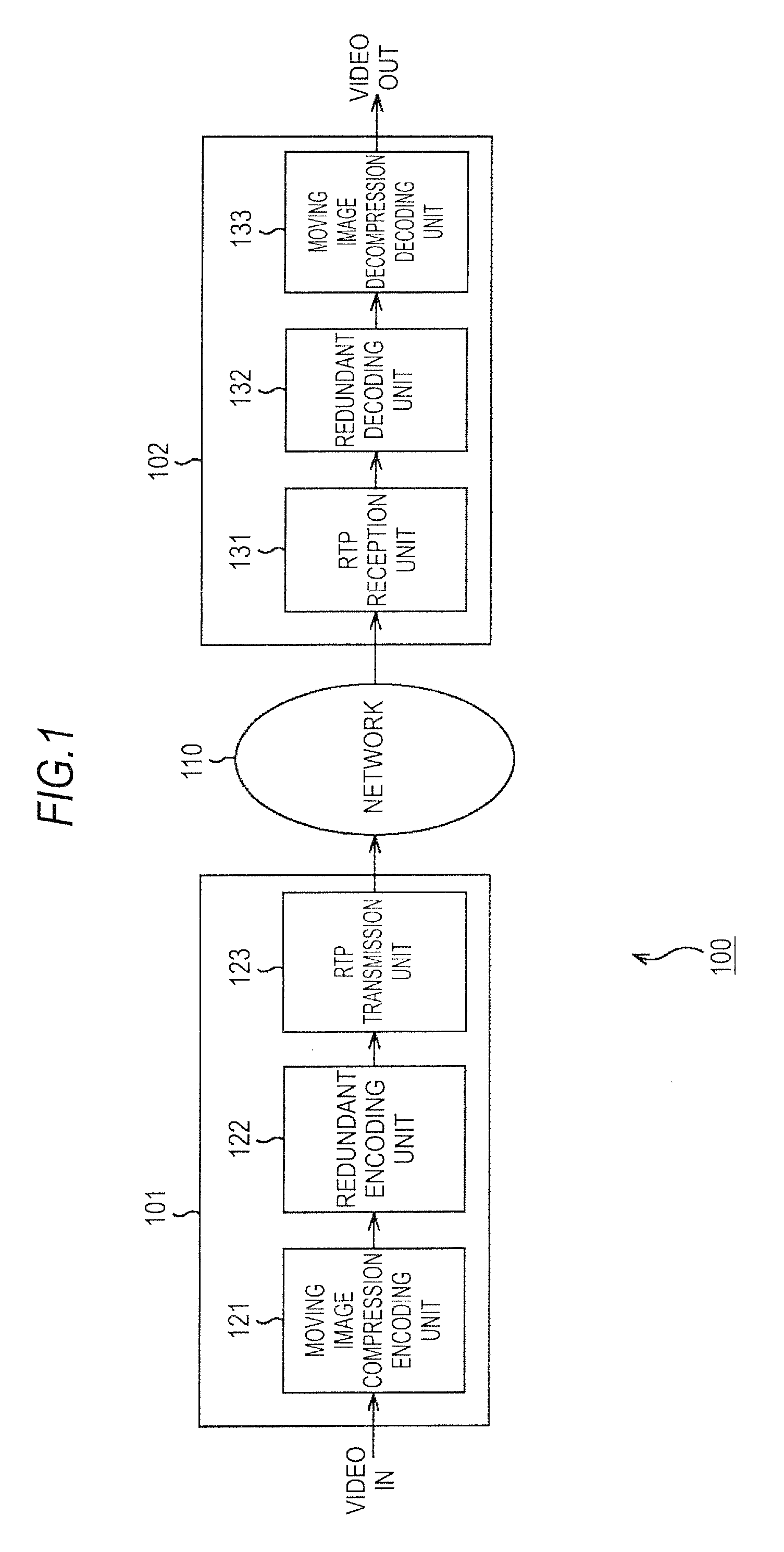
[0087]FIG. 1 is a block diagram illustrating a configuration example of a network system according to an embodiment of the present invention.

[0088]In FIG. 1, a network system 100 is a system in which image data (moving image data or still image data) is transmitted from a transmission device 101 to a reception device 102 via a network 110. Hereinafter, although a case of transmitting moving image data will be described for convenience of description, the following description is applicable to transmission of still image data. A moving image is thought to be frame images or a set of field images, that is, a set of still images. Therefore, the network system 100 can transmit the still image data by performing fundamentally the same manner as a case of transmitting moving image data described below.

[0089]The transmission device 101 packetizes input moving image data (video IN) through encoding, and transmits the packets to the recepti...

second embodiment

2. Second Embodiment

[Configuration of Redundant Decoding Unit]

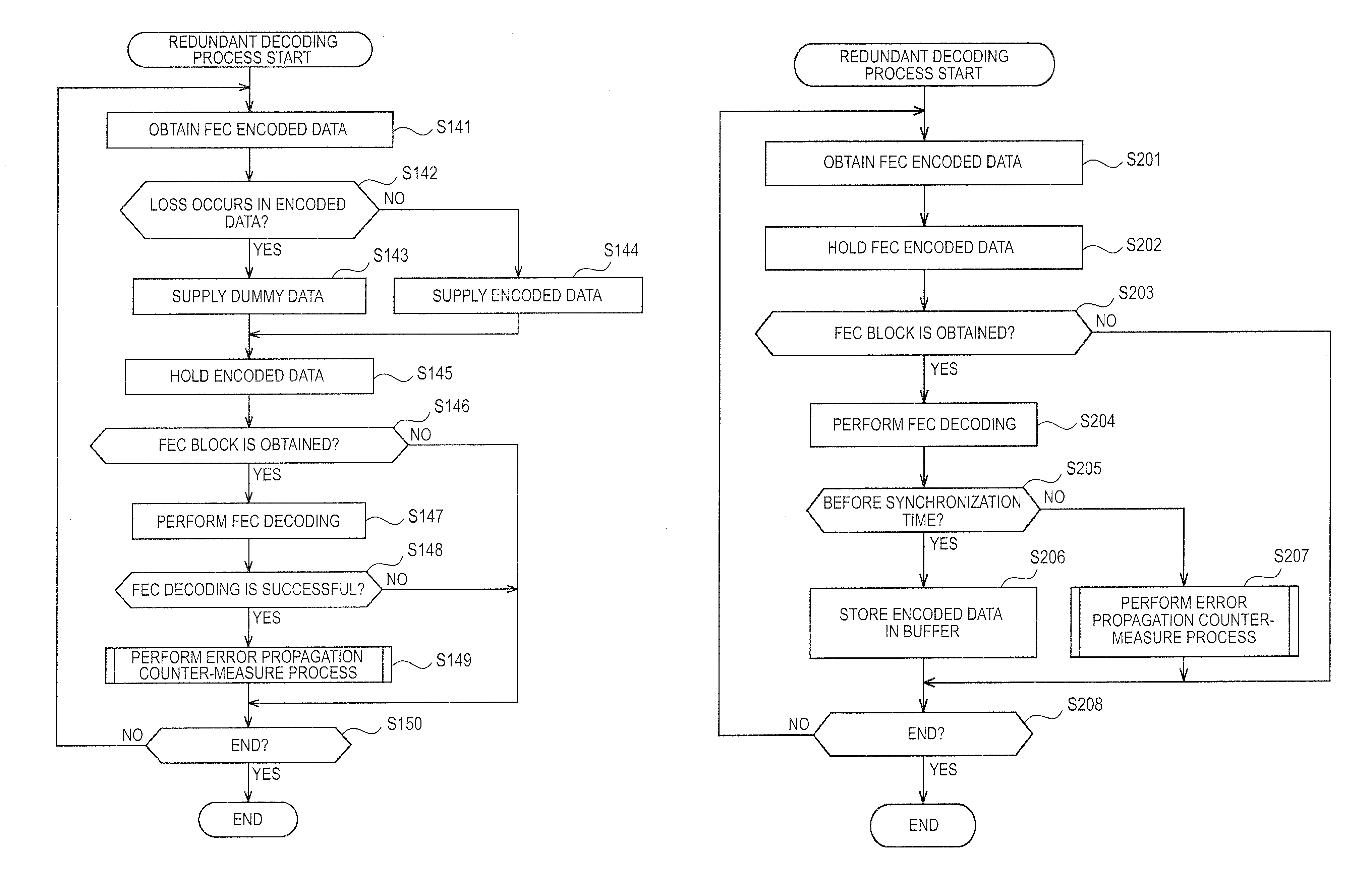
[0270]In addition, the method for recovering lost data in the same manner as the related art and the method for suppressing the error propagation described in the first embodiment may be used together. For example, the reception device 102 performs synchronous reproduction. If an FEC decoding process is performed in line with decoding starting time in a synchronization signal, the FEC decoding process may be performed as a process for data recovery, and the recovered encoded data may be used in a decoding process for the block. If an FEC decoding process is not performed at the decoding starting time in the synchronization signal, the FEC decoding process may be performed as the error propagation counter-measure as described above, and the recovered encoded data may be used in a decoding process for a next block.

[0271]FIG. 22 is a block diagram illustrating a main configuration example of the redundant decoding unit 132 i...

third embodiment

3. Third Embodiment

[Description of Process in Entire System]

[0301]In addition, both of the FEC encoding for suppressing the error propagation as described in the first embodiment and the FEC encoding for recovery as described in the second embodiment may be performed for the encoded data.

[0302]In this case, the network system 100 performs processes as shown in FIG. 25.

[0303]In other words, the moving image compression encoding unit 121 performs the compression encoding process (the arrow 301) and generates, for example, a compressed encoded data block corresponding to each “uncompressed data block”. The redundant encoding unit 122 generates one compressed encoded data block as “FEC block original data for recovery” and generates a compressed encoded data block group corresponding to three “uncompressed data blocks” as “FEC block original data for an error propagation counter-measure” (the arrow 302).

[0304]The number of the redundant packets is arbitrary, and, for example, the number...


PUM


Abstract

An information processing device includes: an obtaining means for obtaining encoded data obtained by encoding image data formed by blocks with predetermined data unit, for each block, and redundant data for the encoded data obtained by encoding the encoded data using a forward error correction method; a decoding means for decoding each block using the encoded data and intermediate data generated during a decoding process if the encoded data is all collected or using dummy data, the encoded data, and intermediate data generated during a decoding process if the encoded data is not all collected; a forward error correction method decoding means for decoding the encoded data and the redundant data and recovers lost encoded data; and a setting means for decoding the encoded data and setting intermediate data obtained during the decoding to be used to decode a subsequent block as intermediate data during a decoding process for a block which has been decoded.

Description

BACKGROUND OF THE INVENTION[0001]1. Field of the Invention[0002]The present invention relates to an information processing device, an information processing method, and an information processing program, and more particularly to an information processing device, an information processing method, and an information processing program, capable of suppressing an increase in unnecessary delay and of suppressing errors from being propagated to subsequent data.[0003]2. Description of the Related Art[0004]In recent years, there has been increasing demand for the transmission of multimedia data with a short delay via the Internet or other transmission paths. For example, there is a so-called remote surgery application in which medical bases of two remote locations are connected to each other via the Internet or the like, the surgical situation is transmitted as moving images from one remote surgery room, and, in the other base, surgical instruments are operated while the images are viewed. ...

Claims


Application Information

Patent Timeline
Patent Type & Authority Patents(United States)
IPC IPC(8): H03M13/00H04L1/00H03M7/30H04N19/31H04N19/33H04N19/36H04N19/60H04N19/635H04N19/65H04N19/89H04N19/895H04N19/91
CPCH04N19/63H04N19/44H04N19/61
Inventor KURE, YOSHINOBU
Owner SONY CORP
Why Eureka
Try Eureka