
Ultrasonic evaluation of venous structures

a technology of venous structure and ultrasonic evaluation, which is applied in the direction of sensors, catheters, diagnostics, etc., can solve the problems of increasing the current challenges of vascular access, and achieve the effect of improving the vascular access ra

Active Publication Date: 2013-09-10
ST MICHAELS HOSPITAL
View PDF12 Cites 1 Cited by
  • Summary
  • Abstract
  • Description
  • Claims
  • Application Information

AI Technical Summary

Benefits of technology

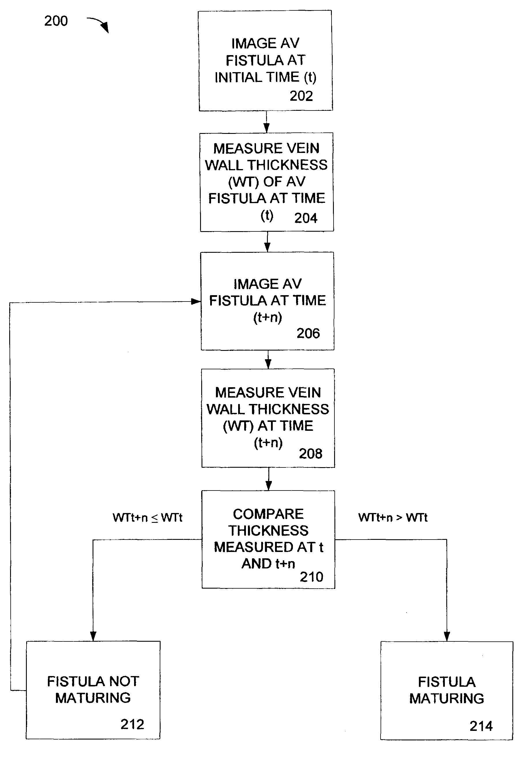
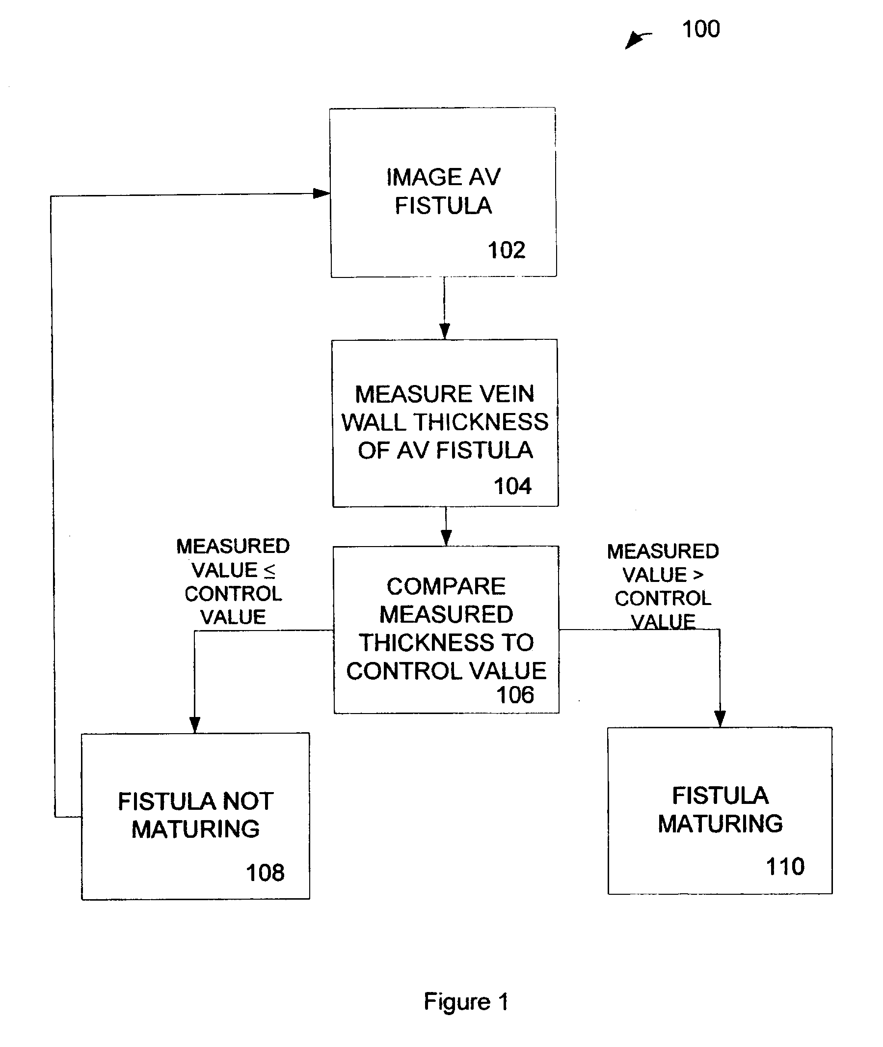
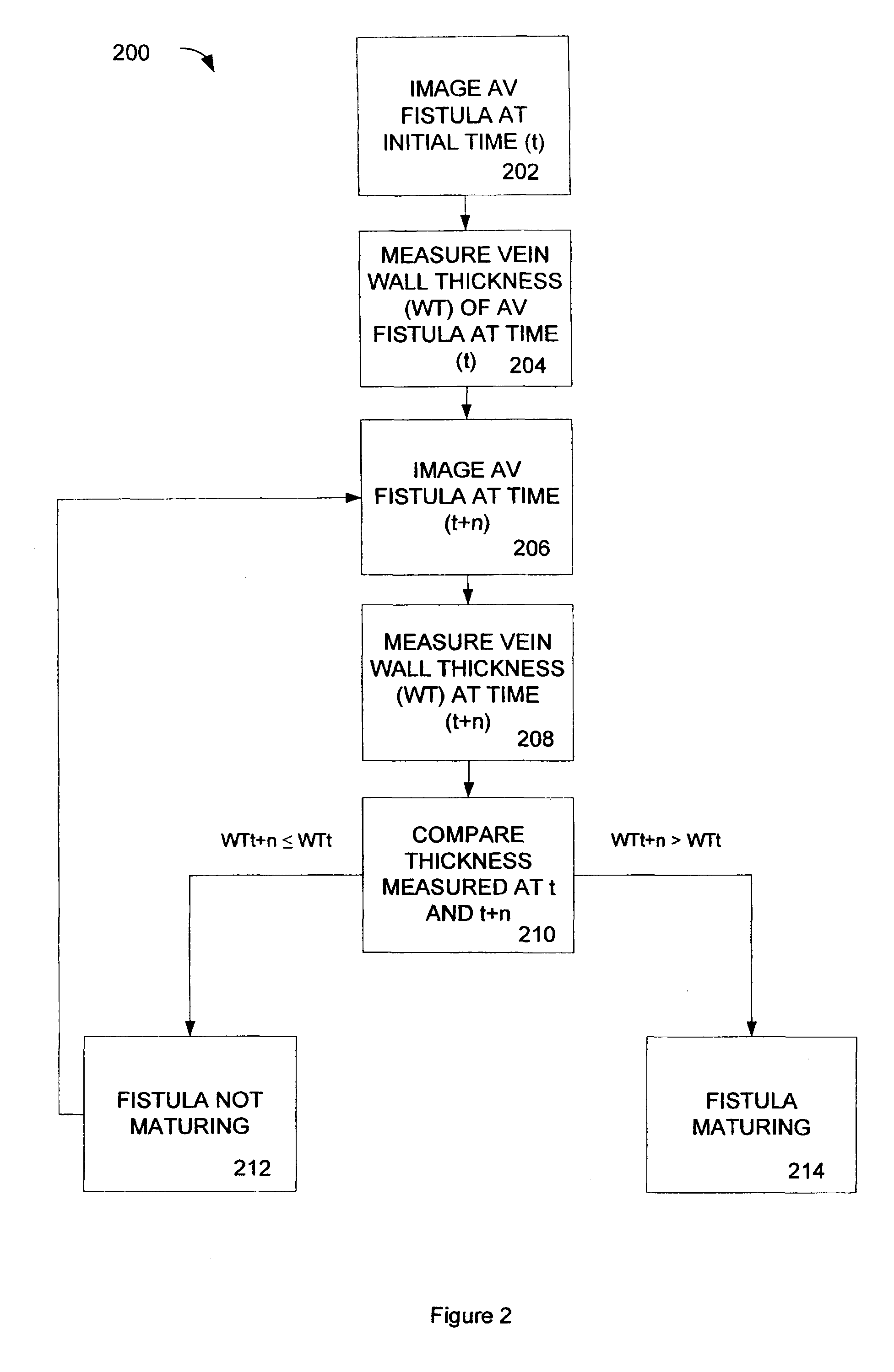
The patent text describes methods and systems for detecting when an arterio-venous fistula (a connection between an artery and a vein) is maturing or has matured. The technical effect is that these methods and systems can help improve the care and treatment of patients with this condition by allowing for earlier detection and intervention. Additionally, the patent text also describes methods and systems for detecting the thickening of a vein wall, which can also aid in the diagnosis and treatment of patients with this condition.

Problems solved by technology

Moreover, the current challenges of vascular access are expected to increase over time as the typical incident patients are older and have more co-morbid vascular and metabolic disease.

Method used


Image

  • Ultrasonic evaluation of venous structures
  • Ultrasonic evaluation of venous structures
  • Ultrasonic evaluation of venous structures

Examples


example 1

[0068]An exemplary process 400 for analyzing an arterio-venous fistula is shown in FIG. 4. A fistula is longitudinally scanned from the left side and an approximate length is recorded as shown in blocks 402, 404 and 406 respectively. The ultrasound beam is directed perpendicular to the near wall. The minimal luminal diameter and maximal luminal diameter is obtained as shown in block 408. Blood velocity is measured by pulsed Doppler upstream from AVF (arterial end) as shown in block 410. Blood velocity is measured by pulsed Doppler downstream from AVF (venous end) as shown in block 412. Blood velocity is measured by pulsed Doppler within the AVF as shown in block 414. The maximal wall thickness of AVF is measured and the minimal wall thickness of AVF is measured as shown in block 416. Collateral veins within approximately 3.0 cm from the anastomosis are identified as shown in block 418. The process steps can be repeated with an image created from the right side of the fistula as show...

example 2

[0069]A second exemplary process 500 for analyzing an arterio-venous fistula is shown in FIG. 5. A longitudinal ultrasound image of the AVF is captured from the left side as shown in blocks 502, 504, and 506. Measurements from the images on the left side views of the AVF are performed. On the near wall of the AVF a caliper is placed on the bottom of the adventitia (the bottom of the first bright reflection line) and the interface is traced for a 5-7 mm length segment as shown in block 508 and in FIG. 6. A second caliper is placed at the interface where the intima / media meets the lumen (the bottom of the second bright reflection line) and this interface is traced for the same 5-7 mm length as shown in block 518 and in FIG. 6. On the far wall of the AVF a third caliper is placed at the interface where the lumen meets the intima / media (the top the first bright reflection line) and this segment is traced for the same 5-7 mm length as shown in block 512 and in FIG. 6. A fourth caliper is...


PUM


Abstract

Provided are methods and systems for detecting a maturing arterio-venous fistula comprising a vein. An exemplary method comprises determining a wall thickness of the fistula and a lumen diameter of the fistula vein using a high frequency ultrasound imaging system. A blood pressure of the subject is determined. A circumferential vessel wall stress is determined from the measured blood pressure, the wall thickness of the fistula and a determined radius of the measured diameter of the fistula. The determined circumferential vessel stress is compared to a predetermined threshold stress to determine if the fistula is mature.

Description

CROSS-REFERENCE TO RELATED APPLICATIONS[0001]This application is the National Stage of International Application No. PCT / CA2007 / 000986, filed Jun. 1, 2007, which claims the benefit of U.S. Provisional Application No. 60 / 810,246 filed Jun. 2, 2006, which is incorporated herein by reference in its entirety.BACKGROUND OF THE INVENTION[0002]The need for access to the circulation is paramount for delivery of renal replacement therapy (RRT) by hemodialysis. The use of a native arterio-venous (AV) fistula provides access with the fewest complications of thrombosis, infection and hospitalization. The creation of the AV fistula is followed by a maturing time in which vascular remodeling occurs. The natural history of this process is not well defined. Moreover, the current challenges of vascular access are expected to increase over time as the typical incident patients are older and have more co-morbid vascular and metabolic disease.SUMMARY OF THE INVENTION[0003]Provided are methods and syste...

Claims


Application Information

Patent Timeline
Patent Type & Authority Patents(United States)
IPC IPC(8): A61B8/00
CPCA61B5/02007A61B5/1075A61B8/0858A61B8/5223A61B8/06A61B8/14A61B8/4483A61B8/5207A61B8/04A61B5/02A61M1/3655A61B8/461
Inventor DONNELLY, SANDRAMURADALI, DEREK
Owner ST MICHAELS HOSPITAL
Learn More