Light emitting device, resin package, resin-molded body, and methods for manufacturing light emitting device, resin package and resin-molded body

a technology of light emitting devices and resin parts, which is applied in the direction of solid-state devices, basic electric elements, coatings, etc., can solve the problems of low resin fluidity of thermosetting resin, low adhesion of thermoplastic resin to lead frame, and easy detachment of resin parts and lead frame, etc., to achieve short time, improve production efficiency, and high adhesion

Active Publication Date: 2013-09-10
NICHIA CORP
View PDF20 Cites 29 Cited by
  • Summary
  • Abstract
  • Description
  • Claims
  • Application Information

AI Technical Summary

Benefits of technology

[0034]The light emitting device and manufacturing method therefor according to the present invention can provide a light emitting device which provides high adhesion between a lead frame and a resin-molded body. Further, it is possible to provide multiple light emitting devices in a short time and greatly improve production efficiency. Furthermore, it is possible to reduce runners which are discarded, and provide light emitting devices at low cost.

Problems solved by technology

However, the thermoplastic resin has little adhesion with a lead frame, and the resin part and lead frame are likely to be detached.
Further, the thermosetting resin has lower resin fluidity of the resin and therefore is not adequate to mold a resin-molded body of a complicated shape, and has little light resistance.
However, this manufacturing method has difficulty in manufacturing multiple light emitting devices in a short time.
Further, there is a problem that a great amount of a resin of a runner part is discarded per one light emitting device.
However, these wiring board and lead frame have a flat plate shape and have a small adhering area because a thermosetting resin composition is arranged on this flat shape, and therefore there is a problem that, for example, a lead frame and thermosetting resin composition are likely to be detached upon singulation.

Method used


Image

  • Light emitting device, resin package, resin-molded body, and methods for manufacturing light emitting device, resin package and resin-molded body
  • Light emitting device, resin package, resin-molded body, and methods for manufacturing light emitting device, resin package and resin-molded body
  • Light emitting device, resin package, resin-molded body, and methods for manufacturing light emitting device, resin package and resin-molded body

Examples


first embodiment

[0036](Light Emitting Device)

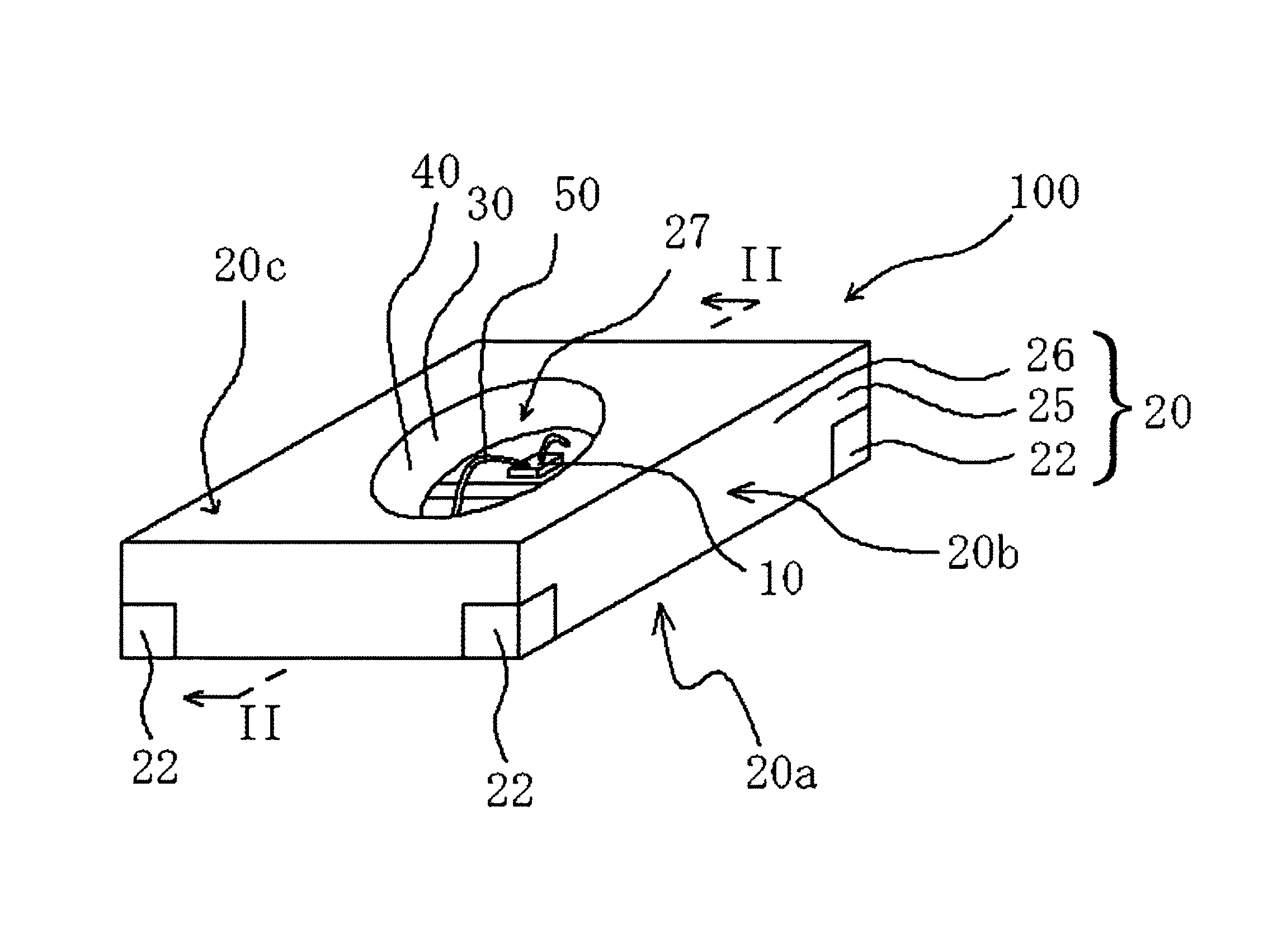
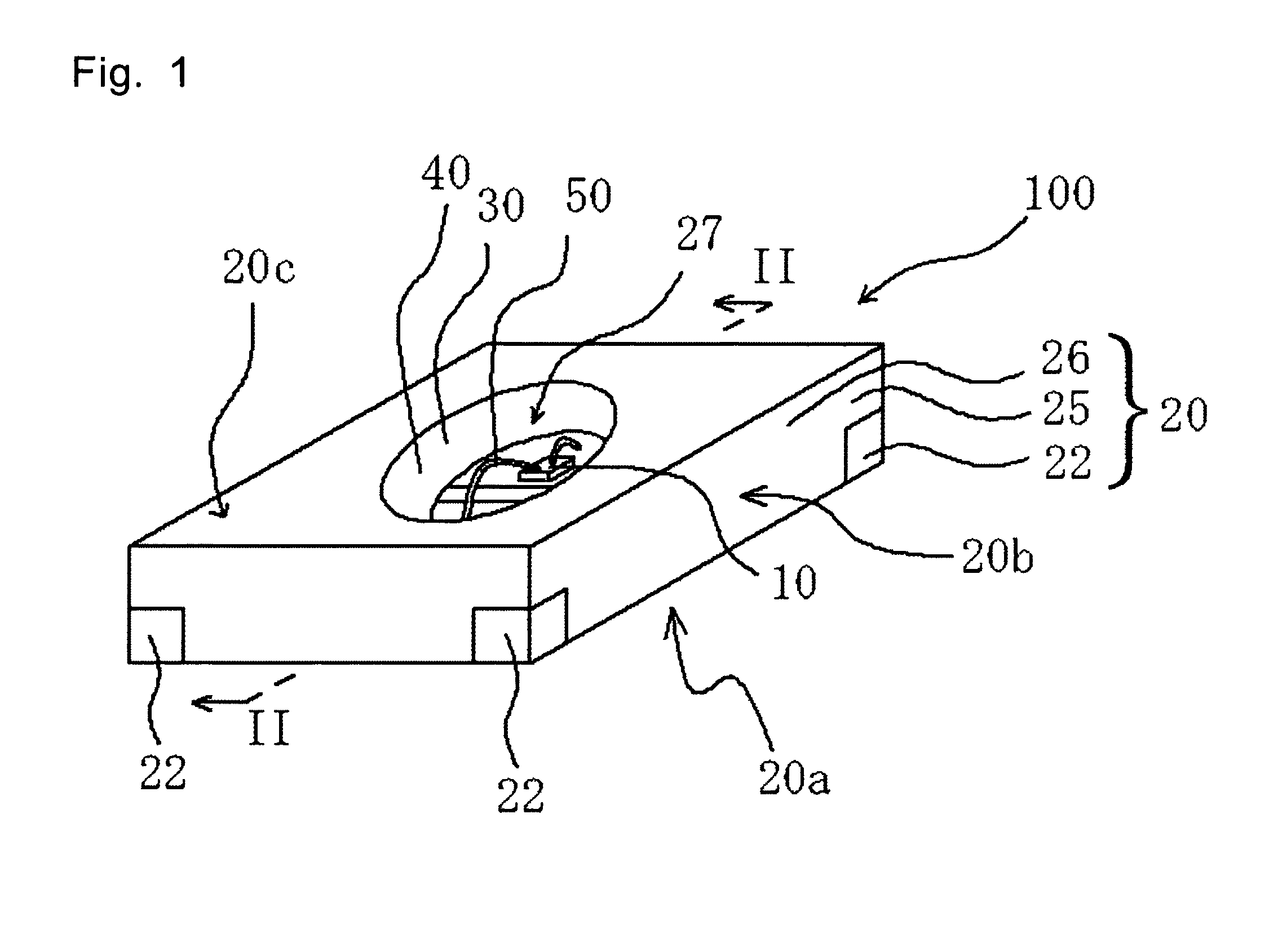
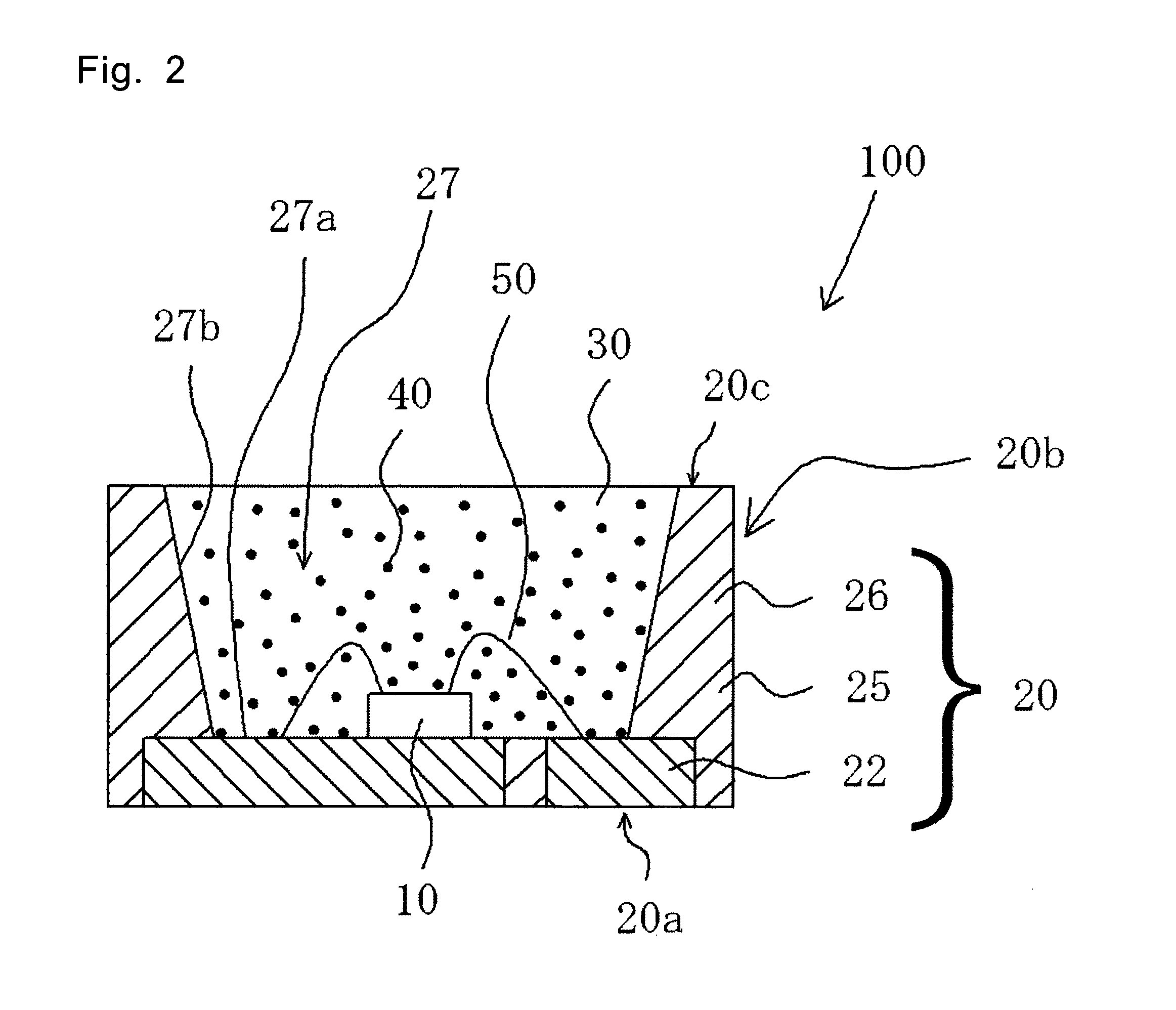
[0037]A light emitting device according to a first embodiment will be described. FIG. 1 is a perspective view illustrating a light emitting device according to the first embodiment. FIG. 2 is a sectional view illustrating a light emitting device according to the first embodiment. FIG. 2 is a sectional view taken along line II-II illustrated in FIG. 1. FIG. 3 is a plan view illustrating a lead frame used in the first embodiment.

[0038]A light emitting device 100 according to the first embodiment provides an optical reflectivity equal to or greater than 70% at the wavelength between 350 nm and 800 nm after thermal curing, and has a resin package 20 in which a resin part 25 and leads 22 are formed in the substantially same plane in outer side surfaces 20b. Plating processing is applied to at least one surface of the bottom surface (an outer bottom surface 20a of the resin package 20) and the upper surface (an inner bottom surface 27a of a concave part 27) of...

second embodiment

[0099]A light emitting device according to a second embodiment will be described. FIG. 6 is a perspective view illustrating a light emitting device according to the second embodiment. FIG. 7 is a plan view illustrating a lead frame used in the second embodiment. FIG. 8 is a plan view illustrating a resin-molded body according to the second embodiment. Description of some configurations employing the substantially same configuration as the light emitting device according to the first embodiment will be omitted where necessary.

[0100]With the light emitting device according to the second embodiment, the light emitting element 10 is placed in the concave part provided in the resin package 120. The corner parts of the outer upper surface 120c of the resin package 120 are formed in an arc shape. Further, the side surface of the lead 122 is formed in an arc shape seen from the upper surface, and the lead 122 is provided with a step such that the lead 122 slightly projects from the resin pa...

third embodiment

[0109]A light emitting device according to a third embodiment will be described. FIG. 9 is a perspective view illustrating the light emitting device according to the third embodiment. FIG. 10 is a plan view illustrating a lead frame used in the third embodiment. Description of some configurations employing the substantially same configuration as the light emitting device according to the first embodiment will be omitted where necessary.

[0110]The light emitting device according to the third embodiment provides an optical reflectivity equal to or greater than 70% at the wavelength between 350 nm and 800 nm after thermal curing, and has a resin package 220 in which a resin part 225 and leads 222 are formed in the substantially same plane in an outer side surface 220b. Plating processing is applied to the bottom surface and upper surface of the leads 222, and is not applied to the outer side surfaces. The lead 222 has a predetermined thickness, and is provided with differences in level ...


PUM

PropertyMeasurementUnit
wavelengthsaaaaaaaaaa
optical reflectivityaaaaaaaaaa

Abstract

Provided is a simple and low-cost method for manufacturing, in a short time, many light emitting devices wherein adhesiveness between a leadframe and a thermosetting resin composition is high. The method for manufacturing the light emitting device having a resin package (20) wherein the optical reflectivity at a wavelength of 350-800 nm after thermal curing is 70% or more and a resin section (25) and a lead (22) are formed on substantially a same surface on an outer surface (20b) has: a step of sandwiching a leadframe (21) provided with a notched section (21a) by an upper molding die (61) and a lower molding die (62); a step of transfer-molding a thermosetting resin (23) containing a light-reflecting substance (26), in a molding die (60) sandwiched by the upper molding die (61) and the lower molding die (62) and forming a resin-molded body (24) on the leadframe (21); and a step of cutting the resin-molded body (24) and the leadframe (21) along the notched section (21a).

Description

CROSS-REFERENCE TO RELATED APPLICATIONS[0001]This application is a National Stage application of PCT / JP2009 / 004170, filed Aug. 27, 2009, which claims priority from Japanese application JP 2008-225408, filed Sep. 3, 2008.TECHNICAL FIELD[0002]The present invention relates to a light emitting device used for light equipment, a display, a backlight of a mobile telephone, a movie lighting auxiliary light source, and other general consumer light sources, and to a method for manufacturing a light emitting device.BACKGROUND ART[0003]A light emitting device using light emitting elements is small, provides good power efficiency, and emits light of bright color. Further, the light emitting elements are semiconductor elements, and therefore there is no concern for blowout. The light emitting elements have characteristics of good initial driving performance and are robust against vibration and repetition of on and off of lighting. The light emitting elements have these good characteristics, and ...

Claims


Application Information

Patent Timeline
Patent Type & Authority Patents(United States)
IPC IPC(8): H01L21/00
CPCB29C45/0055H01L33/60H01L33/486H01L33/62B29C45/14655H01L24/97H01L2924/181B29C2793/009H01L2933/0033H01L2933/0066H01L2224/48091H01L2224/48247H01L2224/48257H01L2924/12035H01L2924/3025H01L2924/12042H01L2924/12041H01L2924/00014H01L2924/00H01L2924/00012H01L33/0095H01L33/504H01L33/56H01L33/641H01L33/48H01L33/54H01L2933/005H01L23/49575H01L23/49548H01L23/49582
Inventor ICHIKAWA, HIROFUMIHAYASHI, MASAKISASAOKA, SHIMPEIMIKI, TOMOHIDE
Owner NICHIA CORP
Why Eureka
Try Eureka