Permanent magnet motor with stator-based saliency for position sensorless drive

a permanent magnet motor and position sensor technology, applied in the direction of motor/generator/converter stopper, dynamo-electric gear control, motor/generator/converter stopper, etc., can solve the problem of reducing the reliability of the motor, reducing the efficiency of current position sensorless detection systems, and reducing the efficiency of spmsm design. problem, to achieve the effect of improving the extraction of sensing spatial signals and reducing interference from drive signals

Active Publication Date: 2013-09-10
WISCONSIN ALUMNI RES FOUND
View PDF8 Cites 0 Cited by
  • Summary
  • Abstract
  • Description
  • Claims
  • Application Information

AI Technical Summary

Benefits of technology

[0012]The present invention provides a motor design in which a saliency is implemented through stator design and, in particular, through design of stator teeth to produce measurable saturation as a function of rotor position. In one embodiment, the stator is designed to be saturated by “zigzag” leakage flux conducted between rotor magnetic poles and thus may be out of phase with the drive current of the stator. This phasing permits improved extraction of the sensing spatial signal with reduced interference from the drive signal. Various embodiments of the invention also provide for preferred winding arrangements and numbers of rotor poles and stator slots.
[0014]It is thus a feature of a least one embodiment of the invention to permit position sensorless operation for motor types having zero or very low saliency in the rotor. By introducing the saliency in the stator, SPMSM sensorless drives may be used effectively.
[0022]It is thus a feature of a least one embodiment of the invention to provide a saturation effect that is largely indifferent to the distal structure of the stator and its coil but instead determined primarily by the stator tip. It is another feature of a least one embodiment of the invention to provide for a saturation that affects the spatial saliency of the motor to be more robust against load changes and drive induced effects that more strongly affect the quadrature phase inductance Lq.
[0024]It is thus a feature of a least one embodiment of the invention to provide a motor harmonic structure that improves the ability to detect the stator-based saliency of the present invention.

Problems solved by technology

Discrete rotor position sensors may substantially decrease the reliability of the motor by introducing additional electrical conductors and connectors that are substantially less robust than the motor windings and their terminations.
Current position sensorless detection systems are relatively ineffective in SPMSM designs which provide a substantially continuous outer magnetic surface.
Many position sensorless systems are susceptible to interference by the drive signal which may obscure sensitive measurements of inductance or reluctance.

Method used


Image

  • Permanent magnet motor with stator-based saliency for position sensorless drive
  • Permanent magnet motor with stator-based saliency for position sensorless drive
  • Permanent magnet motor with stator-based saliency for position sensorless drive

Examples


Embodiment Construction

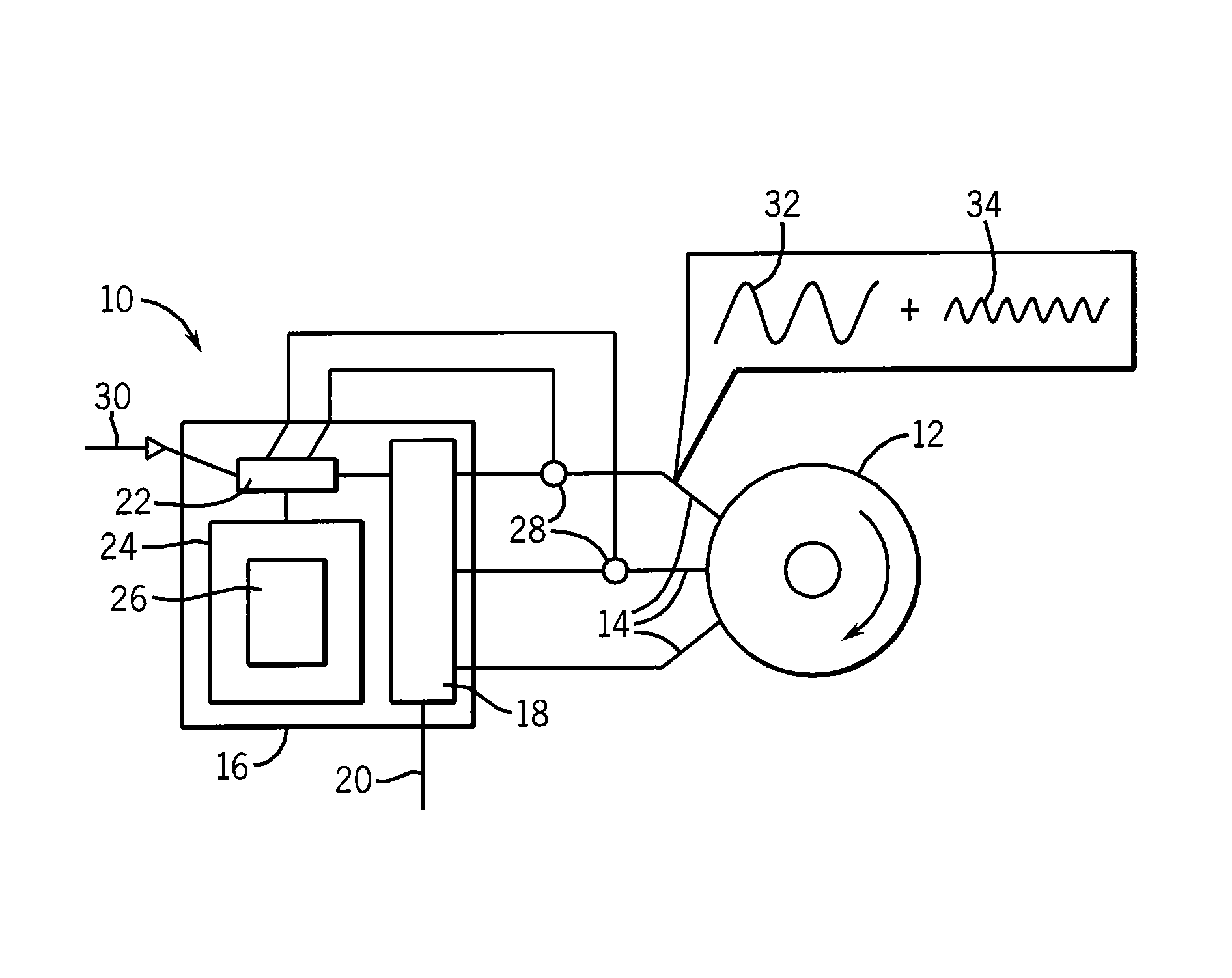
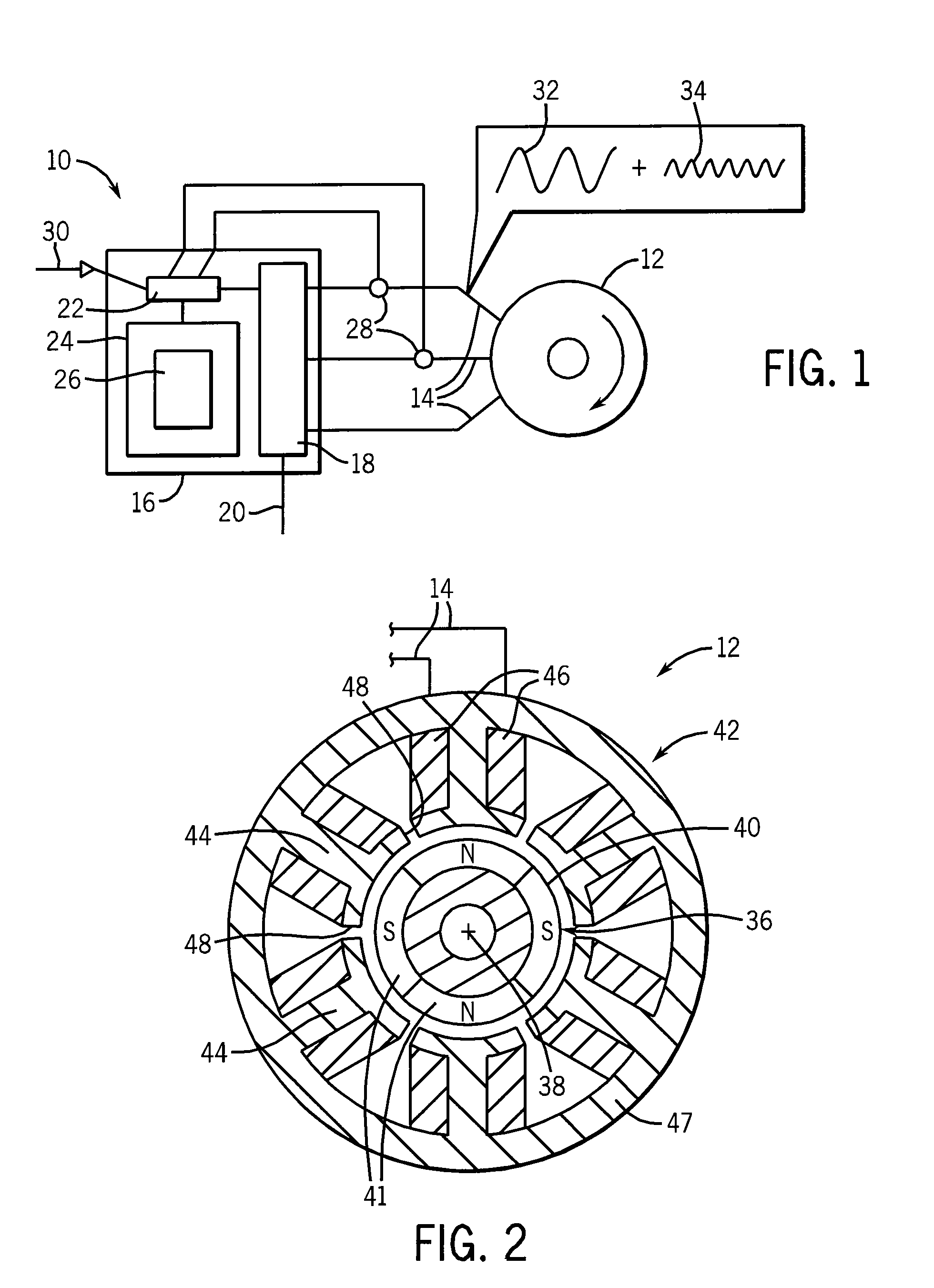
[0040]Referring now to FIG. 1, a position sensorless permanent magnet synchronous motor system 10 may include a permanent magnet motor 12 receiving electrical drive power over leads 14 from a drive system 16.

[0041]The hardware of the drive system 16 may be of conventional design providing drive electronics 18 receiving electrical power 20 and synthesizing, for example using pulse width modulation, arbitrary waveforms on leads 14. The drive electronics 18 may be controlled by a microprocessor 22 or the like communicating with a memory 24 holding a stored program 26 providing for standard control algorithms together with the rotor position-sensing system of the present invention, as will be described in more detail below. The microprocessor 22 may monitor the current through the leads 14 using current sensors 28 and the voltage on the leads 14 via signals provided by the drive electronics 18 for the rotor position-sensing system of the present invention as well as the standard control...


PUM


Abstract

A permanent magnet motor for position sensorless drive operation provides a stator design that exhibits a saliency (machine asymmetric) functionally dependent on rotor position as caused by periodic magnetic saturation of stator structure. This saturation property is caused by rotor zigzag leakage flux from surface permanent magnets. The stator structure may be designed to further saturate from zigzag leakage flux to provide greatest spatial saliency in the quadrature phase for motor position sensorless position estimation. The position, velocity, and shaft torque can be extracted by measuring the phase current from the stator coil of permanent magnet motor.

Description

CROSS-REFERENCE TO RELATED APPLICATIONS[0001]Not applicable.STATEMENT REGARDING FEDERALLY SPONSORED RESEARCH OR DEVELOPMENT[0002]Not applicable.BACKGROUND OF THE INVENTION[0003]The present invention relates to position sensorless permanent magnet motor drives and in particular to a method of sensing rotor position in such motors using stator-based saliency (sometimes referred to as motor asymmetry).[0004]Permanent magnet synchronous motors provide a torque through the interaction of a magnetic field generated by one or more electrical coils and one or more permanent magnet elements. The magnetic field generated by the current supplied to the coils must be synchronized with the position of the magnetic field of the permanent magnets and consequently such motors are normally termed “synchronous motors”.[0005]Permanent magnet synchronous motors place the permanent magnets on the rotor to provide multiple, angularly spaced magnetic poles (eliminating the need for brushes to carry power ...

Claims


Application Information

Patent Timeline
Patent Type & Authority Patents(United States)
IPC IPC(8): H02P6/00
CPCH02K29/06H02P6/186H02P6/183H02P6/181
Inventor YANG, SHIH-CHINSUZUKI, TAKHIROLORENZ, ROBERT DONALDJAHNS, THOMAS MERLIN
Owner WISCONSIN ALUMNI RES FOUND
Why Eureka
Try Eureka