Molecular heater and method of heating fluids

a technology of heating fluid and molecular heater, which is applied in the directions of water supply installation, drawing-off water installation, transportation and packaging, etc., to achieve the effect of reducing microbes in the water

Active Publication Date: 2013-09-10
THERMAL DYNAMIC TECH LLC
View PDF31 Cites 8 Cited by
  • Summary
  • Abstract
  • Description
  • Claims
  • Application Information

AI Technical Summary

Benefits of technology

[0008]The regulator may be in the form of a source of gas bubbles dispersed in the liquid. An increase in gas bubbles reduces the amount of energy delivered to the liquid. The source of gas bubbles may create air bubbles, such as with a venturi tube in the liquid flow path and drawing air from external the liquid. The source of gas bubbles may be another set of conductors connected with the energy source that separate gas from the liquid by breaking at least some molecular bonds of molecules defining the liquid.
[0009]A mono-polar magnet, which may be a permanent magnet or an electro-magnet, may be provided in the liquid stream, such as after the conductors, in order to neutralize polarization of particles in the water created by said electrical energy source operating at relatively low frequency. This prevents the particles from adhering to each other. If it is desired to allow the particles to adhere to each other, in order to make the particles easier to filter from the liquid, the magnet can be eliminated, thereby allowing particles in different portions of the liquid to be oppositely polarized and thereby magnetically attracted to each other. Also, a filter (not shown) may be oppositely charged to further attract the charged particles. Alternatively, multiple oppositely charged paths may be provided downstream of the system to direct charged particles in different directions.
[0010]A housing may be provided to enclose the conductors and liquid flow path. The housing may define a liquid inlet and a liquid outlet and include a ground plane positioned around the liquid inlet, the liquid outlet, or both. This significantly reduces any electric charge in the liquid exiting the system. The housing may be made in whole or in part from an electrically insulating material, such as a polymeric material or of an outer conductive material with a non-conductive spacer between the outer housing and the electrode.
[0011]An electrical liquid heating system and method of heating a liquid, according to the various embodiments of the invention disclosed herein, may have many beneficial applications. For example, it may be used to heat and / or treat the water of a hot tub or a swimming pool. In such an application, the breaking of at least some molecular bonds produces free oxygen that reduces microbes in the water. Also, by adding a salt to the water, the breaking of at least some molecular bonds produces chlorine that further reduces microbes in the water.

Problems solved by technology

The regulator may function by disrupting the delivery of energy to a particular volume of the flowing liquid.

Method used


Image

  • Molecular heater and method of heating fluids
  • Molecular heater and method of heating fluids
  • Molecular heater and method of heating fluids

Examples


Embodiment Construction

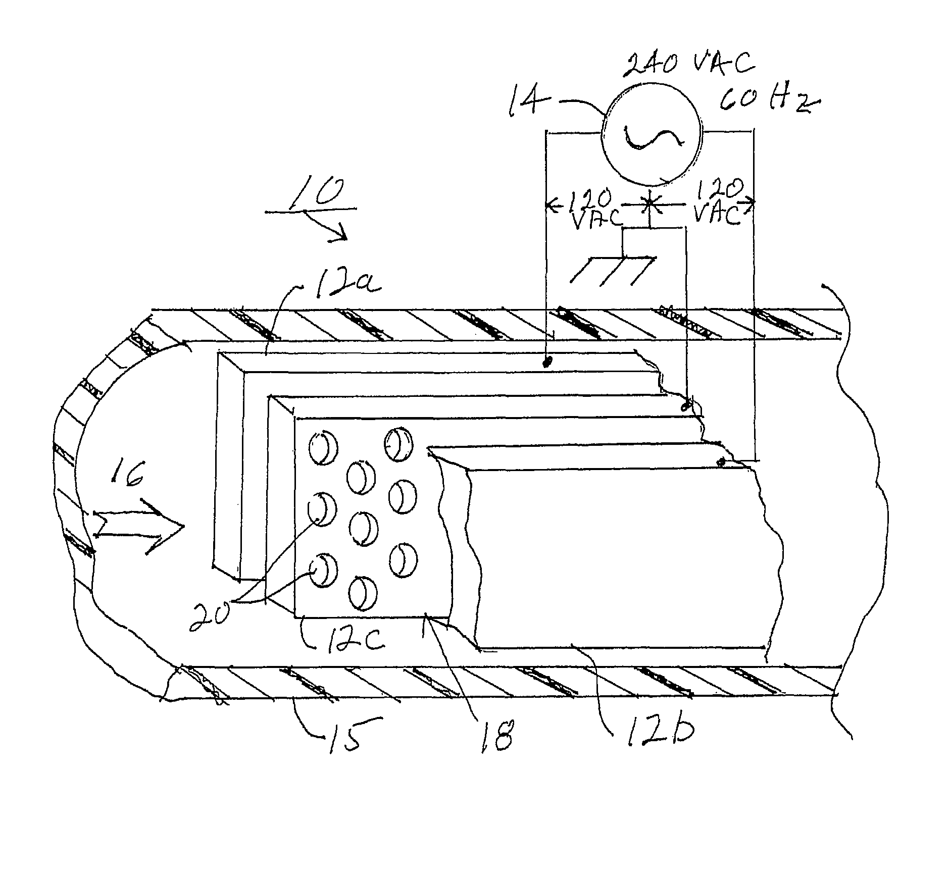
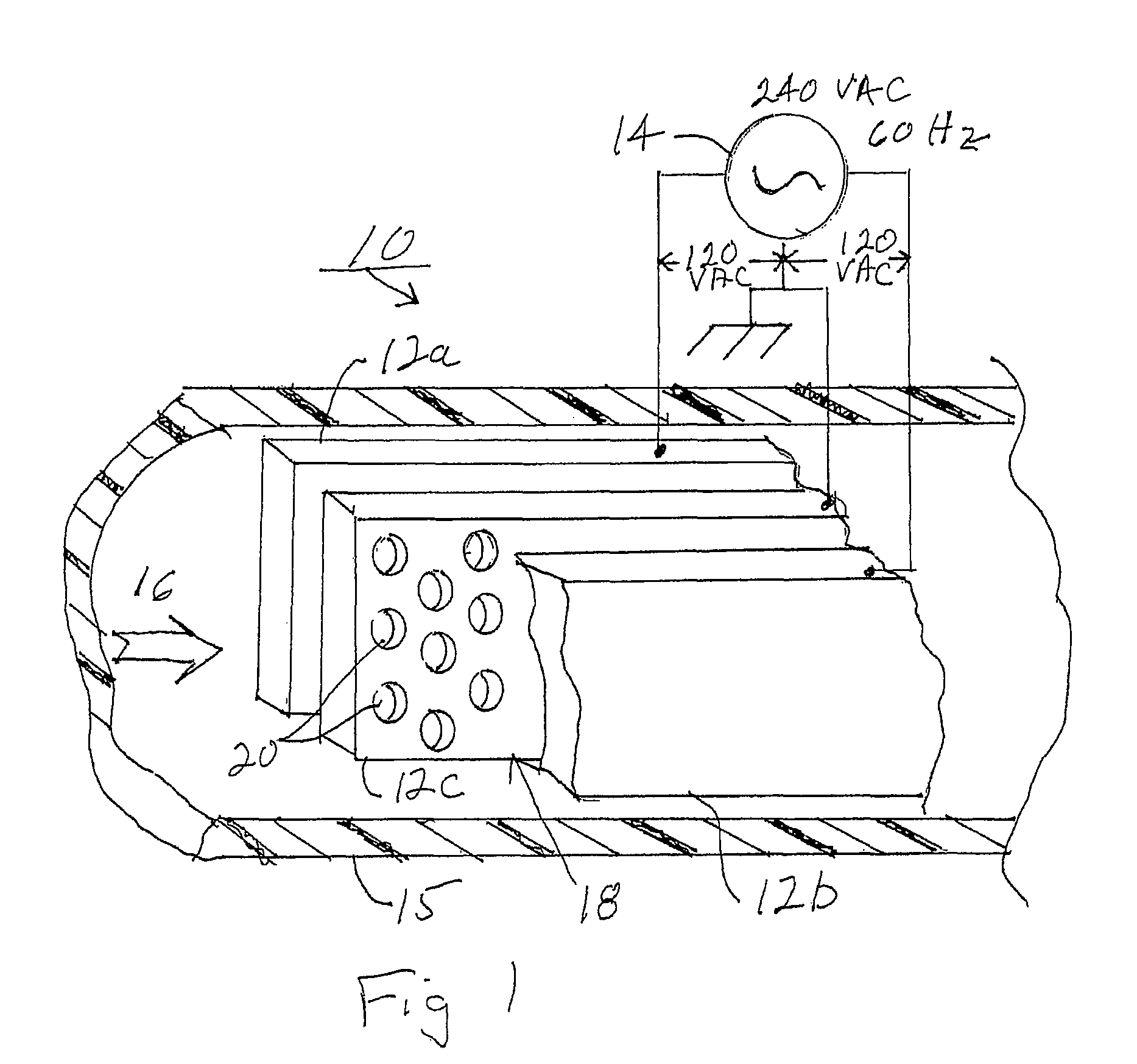
[0025]Referring now specifically to the drawings, and the illustrative embodiments depicted therein, an electrical liquid heating system 10 includes at least two spaced apart electrical conductors 12a and 12b and an electrical energy source 14 applied to the conductors, such as by electrical wiring (FIG. 1). A liquid flow path 16 is provided to direct liquid into contact with conductors 12a, 12b thereby delivering electrical energy to the liquid. As will be described in more detail below, electrical energy source 14 delivers electrical energy to the liquid at a power level that is sufficient to generate an electrical current to produce resistive heating of the liquid. The energy source may further operate at a power level sufficient to break at least some molecular bonds of molecules defining the liquid.

[0026]In the illustrated embodiment, electrical energy source 14 delivers electrical energy at conventional house mains, such as in the range of between 110 volts AC and 240 volts AC...


PUM


Abstract

An electrical liquid heating system and method of heating a liquid includes providing at least two spaced apart electrical conductors and applying an electrical energy source to the conductors. A liquid is directed into contact with the conductors thereby delivering electrical energy to the liquid. Electrical energy is delivered to the liquid at a power level that is sufficient to generate an electrical current to produce resistive heating of the liquid. The electrical energy may be delivered to the liquid at a power level that is sufficient to break at least some molecular bonds of molecules defining the liquid. A regulator may be provided for regulating delivery of electrical energy to the liquid.

Description

CROSS REFERENCE TO RELATED APPLICATION[0001]This application is a filing under 35 U.S.C. §371 of International Application No. PCT / US2009 / 036191 filed Mar. 5, 2009, which claims priority from U.S. provisional patent application Ser. No. 61 / 033,974, filed on Mar. 5, 2008, the disclosures of which are hereby incorporated herein by reference in their entirety.BACKGROUND OF THE INVENTION[0002]The present invention is directed to a heating / evaporating system and method of heating / evaporating a liquid. The invention is also directed to a method of reducing microbes in a liquid.[0003]Traditional electrical resistance heating systems heat and / or evaporate a liquid by generating heat within an electrical resistance element, which heat is transferred to a liquid to either heat the liquid or evaporate the liquid. Because heat is generated by the device, per se, the remainder of the components of the system, such as the housing, or the like, is traditionally made from a metal, Bakelite, or the ...

Claims


Application Information

Patent Timeline
Patent Type & Authority Patents(United States)
IPC IPC(8): H05B3/60E03B9/00
CPCH05B3/60Y10T137/0329
Inventor CAMPBELL, MARK E.
Owner THERMAL DYNAMIC TECH LLC
Why Eureka
Try Eureka