Generation of probe noise in a feedback cancellation system

a technology of feedback cancellation and probe noise, which is applied in the direction of transducer acoustic reaction prevention, sound producing devices, instruments, etc., can solve the problems of slow system adaptation and less accurate estimation of feedback paths

Inactive Publication Date: 2013-09-17
OTICON
View PDF11 Cites 7 Cited by
  • Summary
  • Abstract
  • Description
  • Claims
  • Application Information

AI Technical Summary

Benefits of technology

[0006]It is an object of the invention to propose a scheme for generating an improved probe signal. It is a further object that the probe signal is as close to the ideal as possible. It is a further object that the probe signal uses a minimum of computational power. It is a further object that the scheme is adaptable to the characteristics of an audio input signal. It is a further object to provide a hearing aid comprising a noise generator and a feedback cancellation system comprising an adaptive filter wherein the input reference signals to the adaptive filter are less correlated than without the noise generator. The probe / noise signal will be added to the captured signal, and thereby it will not break the loop, but provide an identification signal for the adaptive algorithm.
[0018]When using the method according to the invention it becomes possible to generate a probe noise signal, which is very close to an ideal noise signal. It will be difficult to hear the probe noise signal when added to the captured audio signal and played to the human ear. The probe noise signal will have the same magnitude spectrum as the ideal signal and it is therefore easily masked by signal components of the audio signal.
[0022]In an embodiment of the invention, the artificial phase values Phase′[U(k)] are substantially un-correlated to phase values Phase[U(k)] of the captured signal. According to an embodiment of the invention, the artificial phase values of the generated probe noise signal in c. are generated by a random generator. This assures that the noise signal is un-correlated with the original signal at all times and irrespective of the properties of the original signal. According to another embodiment of the invention the artificial phase values of the generated probe noise signal in c. are set to a fixed value. This is an easy way to assure that the noise signal is not correlated with the original signal, if the input phase is random (or not fixed). Alternatively, the probe noise signal could be frequency shifted compared to the captured signal. This could be useful at least for a short period, to avoid build up noise from the probe noise system. Alternatively, the artificial phase values of the generated probe noise signal are set to a number of different constant values each corresponding to a different frequency range (e.g. one (e.g. relatively lower) value at lower frequencies and another (e.g. relatively higher) value at higher frequencies).
[0031]Preferably, the overall level of the probe noise signal is controlled by the properties of the captured signal (cf. h.→b.1., cf. FIG. 4). Here it is preferred that the level of the noise signal is lowered when a rapidly changing microphone signal is captured. The generated probe noise is computed from a number of earlier samples of the captured signal. The number is given by the FFT size parameter N_fft. This results in probe noise being added to the output signal with some delay compared to the captured signal. If the level is reduced dramatically after it was captured, the generated noise may be audible as the present level of the microphone signal is lower compared to the captured microphone signal used to compute the probe noise. With a steady input, on the other hand, the features of the captured signal will be similar between captured frames. Then there is no need to reduce the gain. Also the overall noise level and FFT size parameter can be used in the modification of magnitude for masking and the Individual Hearing Threshold (cf. h.→b.2., cf. FIG. 4). With a steady input signal, it can be useful to have a high value of the FFT size to get high frequency resolution and to be able to shape the spectrum of the noise after the signal. With rapid changes in the level of the signal, however, it is more desirable to rapidly change the characteristics of the noise than to have a high frequency resolution. By reducing the FFT size, the probe noise can be changed more rapidly at the expense of a lower frequency resolution.

Problems solved by technology

Lower levels of the reference signal will usually cause less accurate estimation of the feedback path, or slower adaptation of the system.

Method used


Image

  • Generation of probe noise in a feedback cancellation system
  • Generation of probe noise in a feedback cancellation system
  • Generation of probe noise in a feedback cancellation system

Examples


Embodiment Construction

[0064]In the following, embodiments of the invention exemplified in relation to hearing aids are discussed. The examples may likewise be implemented in relation to other audio systems.

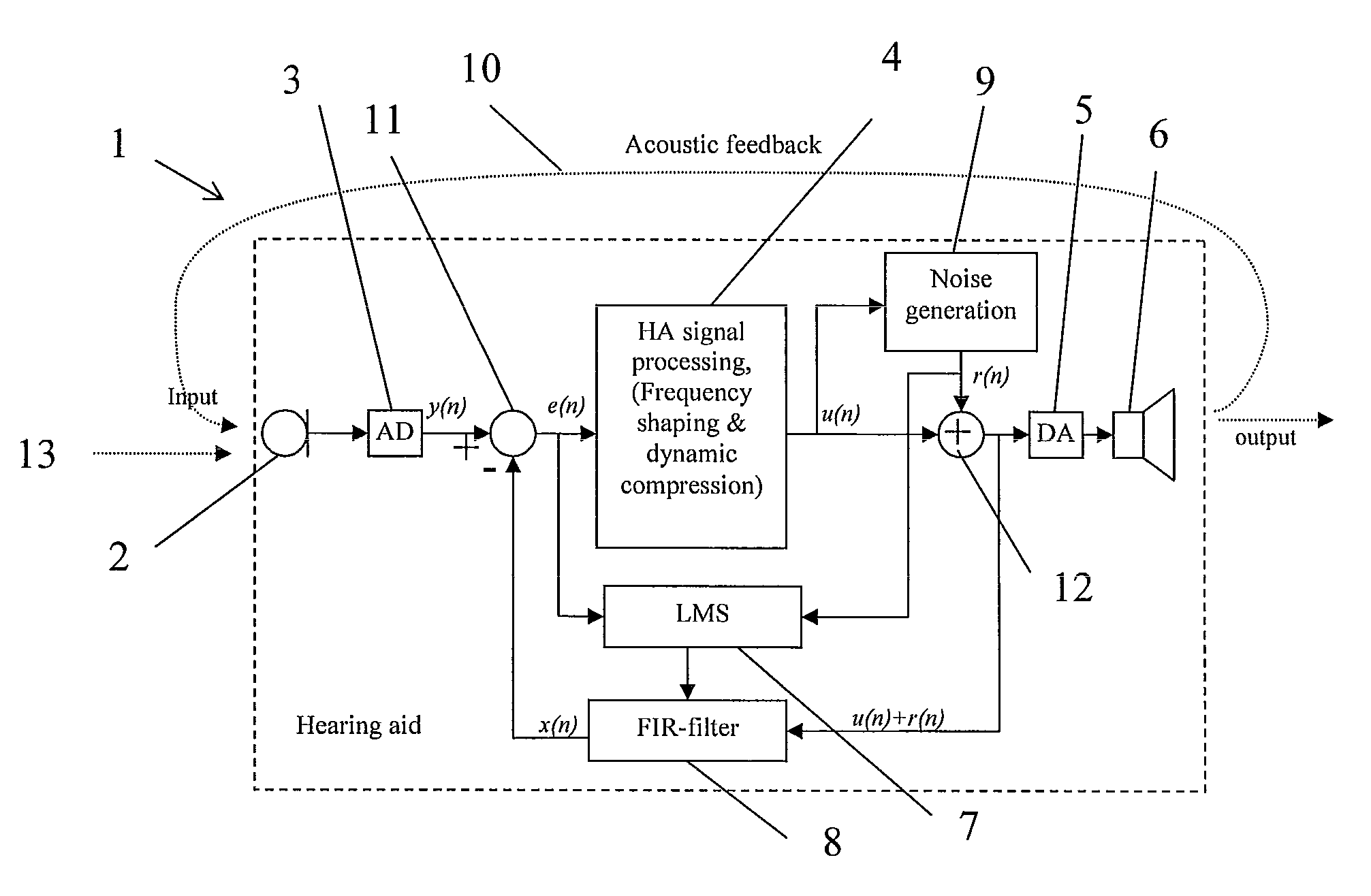
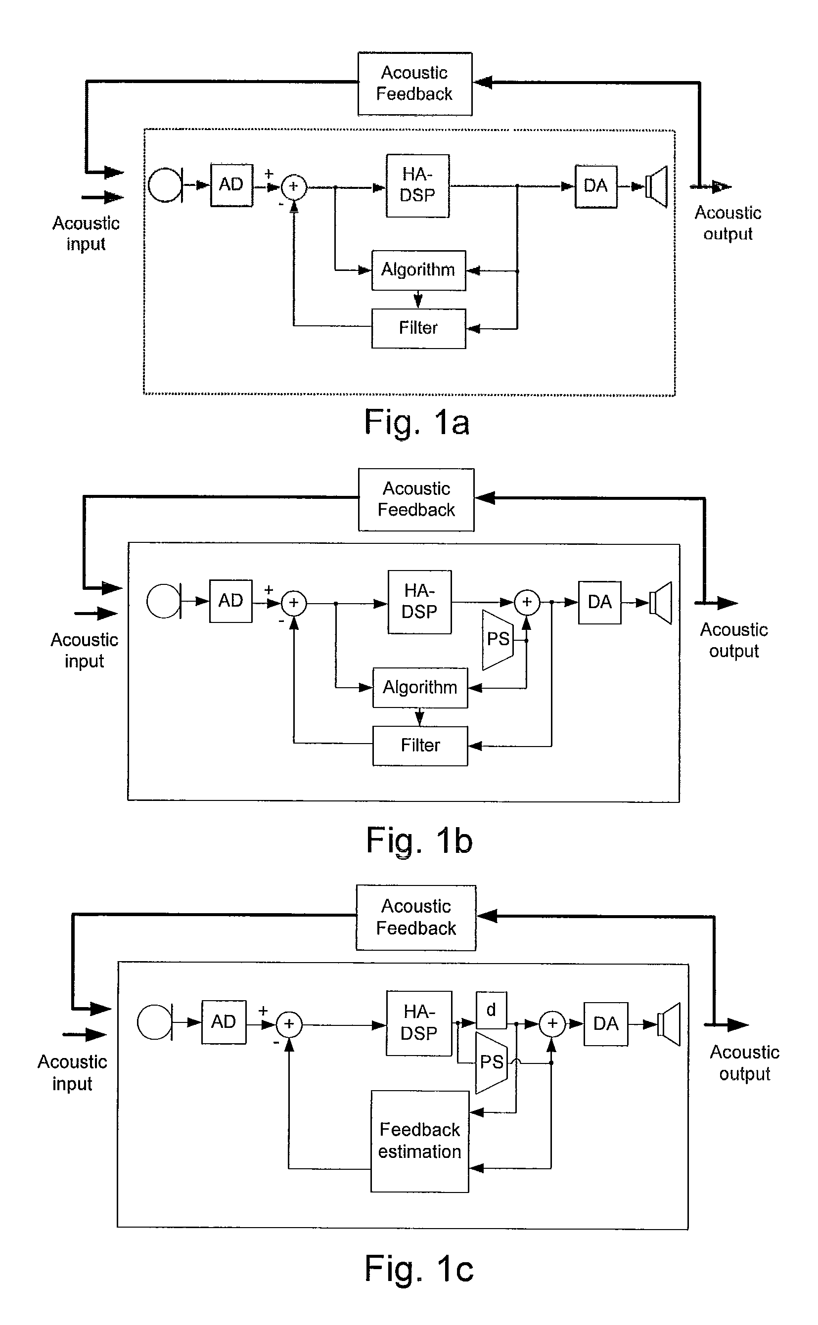
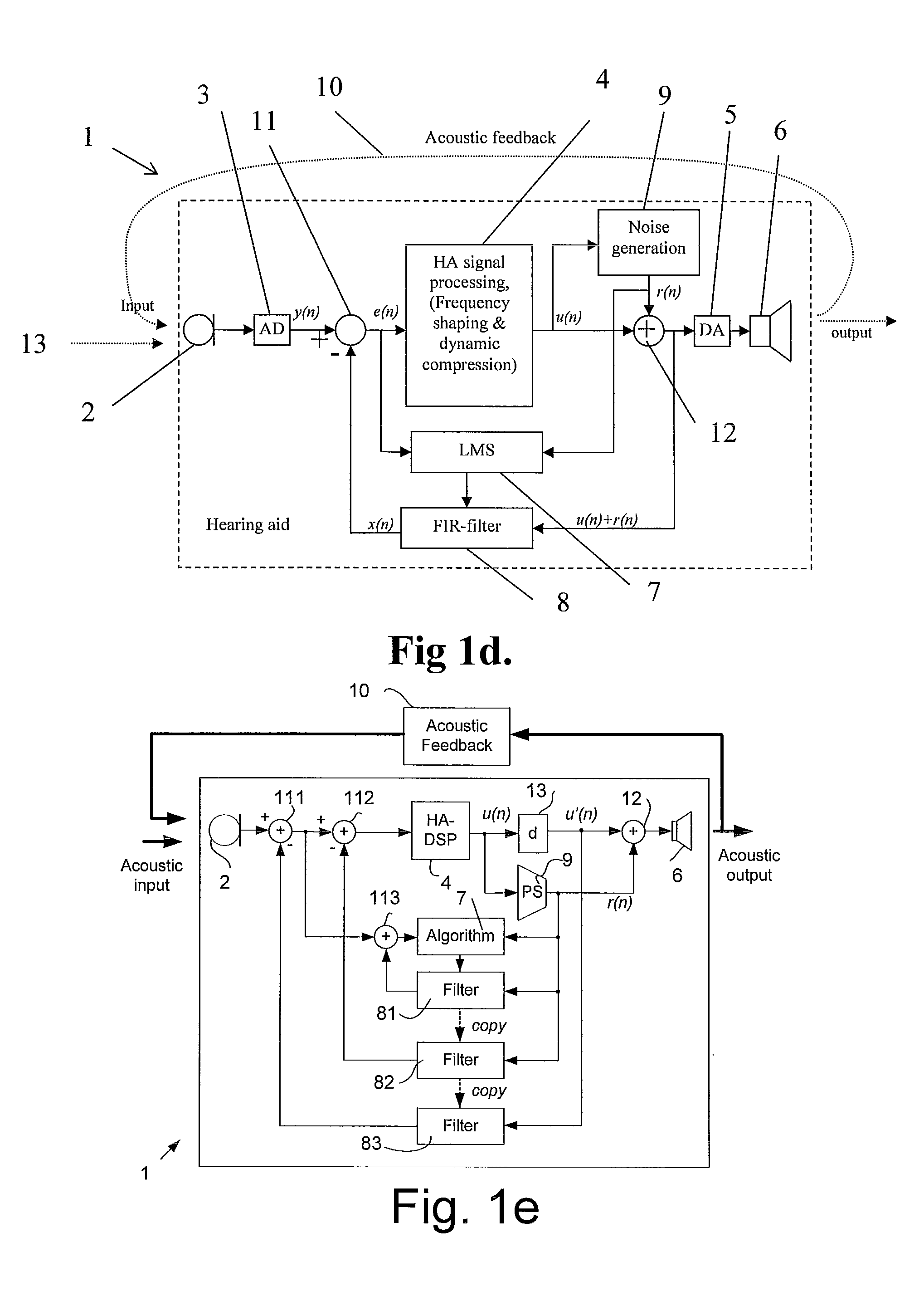
[0065]A hearing aid according to an embodiment of the invention is shown in FIG. 1c, wherein the forward path comprises a microphone a signal processing unit (HA-DSP in FIG. 1c) and receiver. A probe noise generator (PS in FIG. 1c) takes an input from the forward path (here from the output of the signal processing unit) and generates a probe noise signal as described below (cf. e.g. FIGS. 2-4), which is fed to a feedback estimation unit (Feedback estimation in FIG. 1c) as well as being added to the (optionally delayed, cf. block d in FIG. 1c) output from the signal processing unit, the sum of the two signals being converted to an acoustic signal by the receiver. Analogue to Digital (AD) and Digital to Analogue (DA) converters are indicated in the forward path after the microphone and before the receive...


PUM


Abstract

The invention regards a scheme for generating a probe noise signal to be used in an anti feedback system of an audio system. The audio system comprises e.g. a microphone for capturing an audio signal, an audio signal processor for adaptation of the audio signal and a receiver for generation of an audible signal. According to an embodiment of the invention, a noise signal is injected into the audio signal path between the microphone and the receiver and used for estimating acoustical feedback, the noise signal being generated by the following steps:converting a digitized audio signal to the frequency domain, in order to obtain a series of magnitude and phase values,changing the phase values such that the phase of the resulting signal becomes less correlated, preferably substantially un-correlated, to the original signal,converting the magnitude and phase back to a time domain signal using the changed phase values.The invention may e.g. be used in a hearing aid, a headset or a pair of headphones.

Description

AREA OF THE INVENTION[0001]The invention relates to an anti-feedback system, especially to a probe noise signal in an anti-feedback system in an audio system, e.g. a hearing aid, in particular in a sound processor.BACKGROUND OF THE INVENTION[0002]Hearing aid feedback cancellation systems (for reducing or cancelling acoustic feedback from an ‘external’ feedback path from output to input transducer of the hearing aid) according to the prior art may comprise an adaptive filter, which is controlled by a prediction error algorithm, e.g. an LMS (Least Means Squared) algorithm, in order to predict and cancel the part of the microphone signal that is caused by feedback from the receiver of the hearing aid. FIG. 1a illustrates an example of this. The adaptive filter (in FIG. 1 comprising a ‘Filter’ part end a prediction error ‘Algorithm’ part) is aimed at providing a good estimate of the ‘external’ feedback path from the DA to the AD. The prediction error algorithm uses a reference signal to...

Claims


Application Information

Patent Timeline
Patent Type & Authority Patents(United States)
IPC IPC(8): H04R25/00
CPCH04R3/02H04R25/453
Inventor ELMEDYB, THOMAS BOHELLGREN, JOHAN
Owner OTICON
Why Eureka
Try Eureka