Cycloidal rotor with non-circular blade orbit

a cycloid rotor and blade technology, applied in the direction of rotors, marine propulsion, vessel construction, etc., can solve the problems of limited range, high power/fuel requirements compared to the generated lift or thrust, and speed limitations of helicopters, so as to achieve substantially greater lift/thrust, or propulsive force, the effect of improving efficiency

Active Publication Date: 2013-09-24
OPTIVECTOR LTD
View PDF11 Cites 26 Cited by
  • Summary
  • Abstract
  • Description
  • Claims
  • Application Information

AI Technical Summary

Benefits of technology

[0007]An object of the present invention is to provide a cycloidal rotor with improved efficiency resulting in ability to generate substantially greater lift / thrust, or propulsive force per unit of power used.
[0008]Another object of the invention is to provide a rotor that allows the ability to shape the blade orbit / trajectory to maximize or minimize the ratio of lift to thrust when required.
[0009]Another object of the invention is to provide a rotor system that allows differential and variable orbital positioning and spatial orientation of the blades for flexibility in the produced aerodynamic effects suited for various operating regimes and conditions.

Problems solved by technology

However, helicopters have speed limitations, high power / fuel requirements compared to lift or thrust generated, limited range, are noisy, and require a tail rotor which takes up engine power while producing neither lift nor thrust, but rather a sideways force which the pilot must counteract.

Method used


Image

  • Cycloidal rotor with non-circular blade orbit
  • Cycloidal rotor with non-circular blade orbit
  • Cycloidal rotor with non-circular blade orbit

Examples


Embodiment Construction

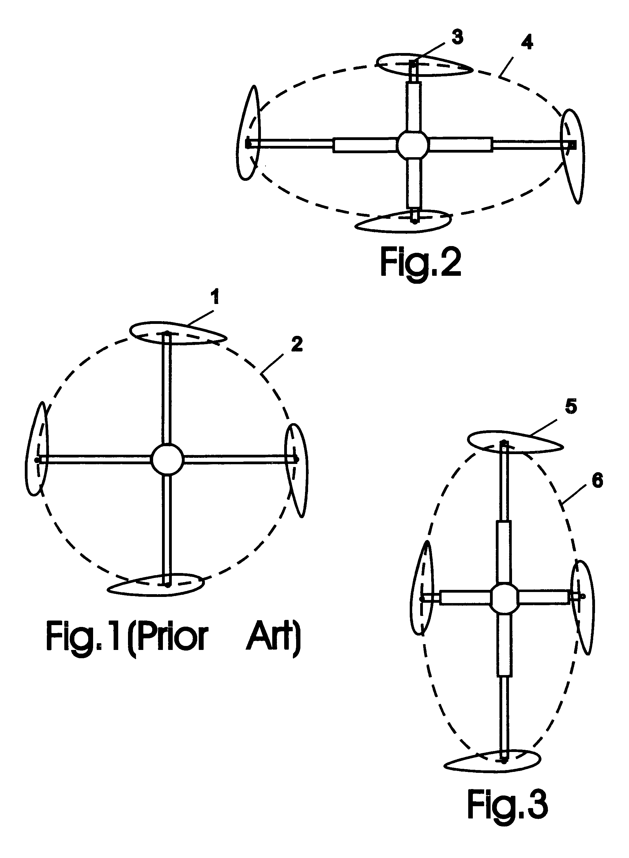
[0025]FIG. 1 illustrates schematically a cycloidal rotor of the prior art, showing the blades 1 following a circular orbit 2. Such rotors can include mechanisms, not shown, that vary the pitch of the individual blade as it orbits.

[0026]FIGS. 2 and 3 illustrates schematically a cycloidal rotor of the present invention showing the difference from the prior art as shown in FIG. 1. Specifically, the blades 3 follow a non-circular, elongated orbit about a central region. In FIG. 2 the blades 3 follow a horizontally elongated orbit 4 suited for high lift, while in FIG. 3 the blades 5 follow a vertically elongated orbit 6 suited for high thrust. To provide the desired orbit, the rotors include mechanisms, not detailed, that vary the radial distance between the blade and the axis of rotation. Examples of mechanisms for providing non-circular orbit are described below.

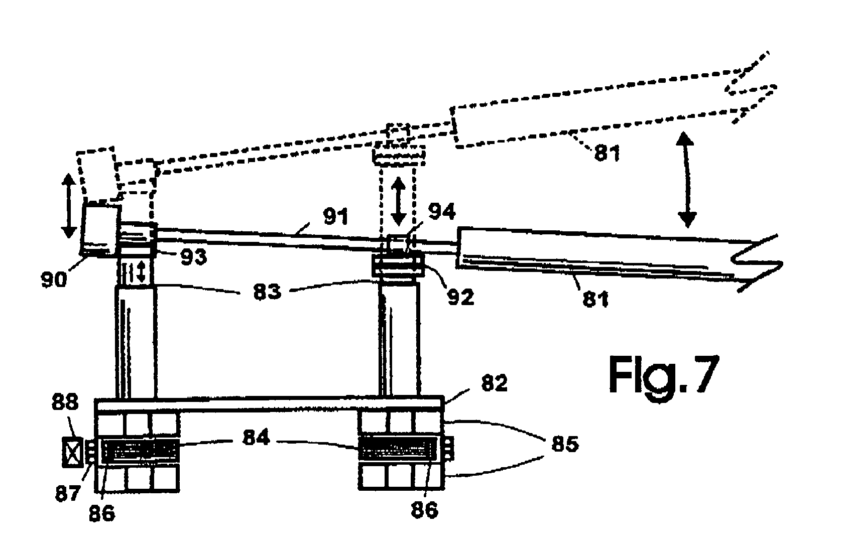
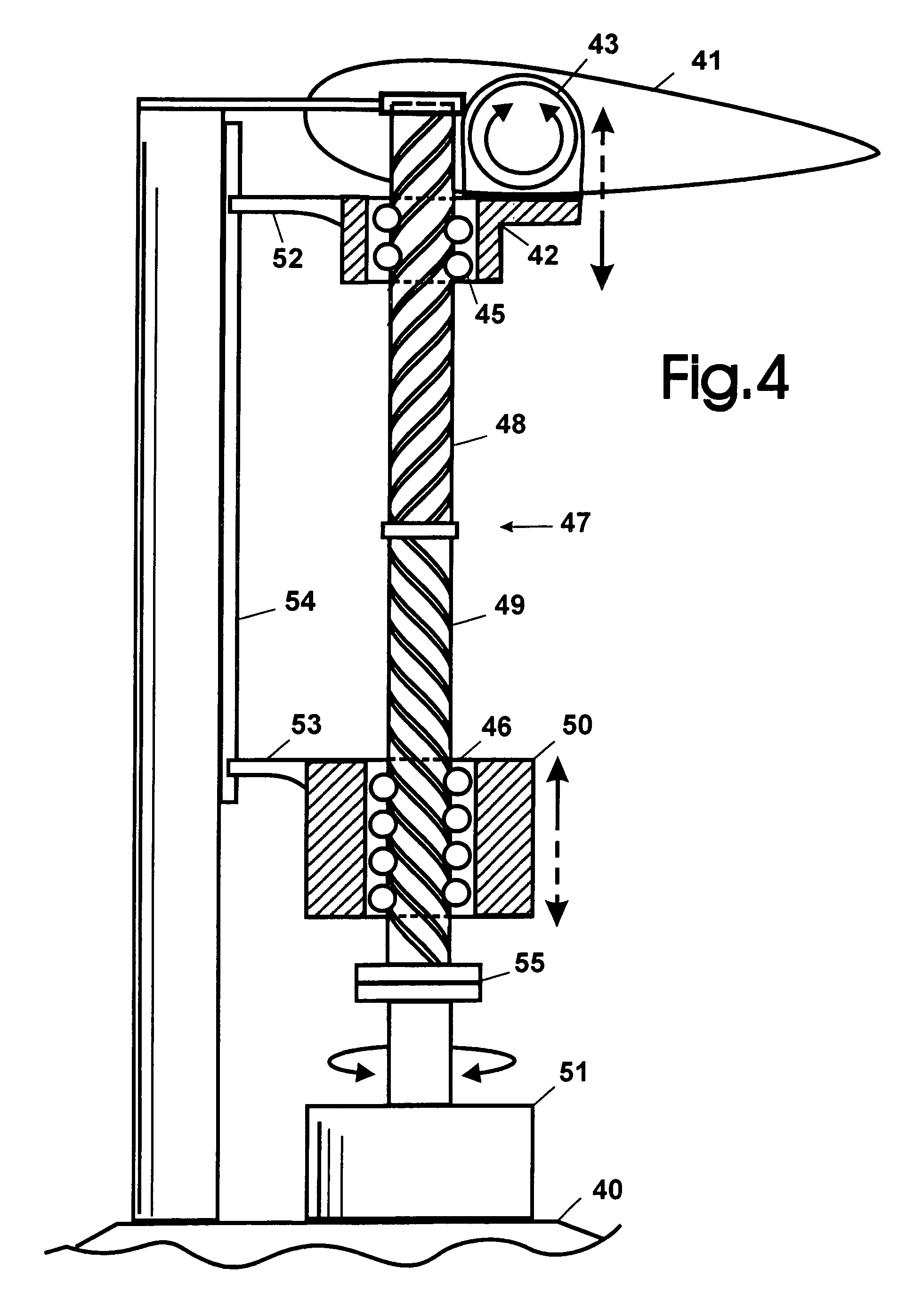
[0027]FIG. 4 illustrates one embodiment of a mechanism for interconnecting the blades (one shown) with hub and providing vari...


PUM


Abstract

A cycloidal rotor system having airfoil blades travelling along a generally non-circular, elongated and, in most embodiments, dynamically variable orbit. Such non-circular orbit provides a greater period in each revolution and an optimized relative wind along the trajectory for each blade to efficiently maximize lift when orbits are elongated horizontally, or thrust / propulsion when orbits are vertically elongated. Most embodiments, in addition to having the computer system controlled actuators to dynamically vary the blade trajectory and the angle of attack, can also have the computer system controlled actuators for dynamically varying the spatial orientation of the blades; enabling their slanting motion upward / downward and / or backsweep / forwardsweep positioning to produce and precisely control a variety of aerodynamic effects suited for providing optimum performance for various operating regimes, counter wind gusts and enable the craft to move sideways. Thus a rotor is provided, which when used in a VTOL rotorcraft, will require lower engine power to match or exceed the operating performance of VTOL rotorcrafts equipped with prior art cycloidal rotors, this rotor also offers increased efficiency and decreased required power when used for generating the propulsive force for various vehicles or used as a fan.

Description

BACKGROUND OF THE INVENTION[0001]1. Field of the Invention[0002]This invention relates to a cycloidal rotor and particularly to a cycloidal rotor that enables the blades to follow a non-circular orbit.[0003]2. Description of the Prior Art[0004]Various types of VTOL aircraft have been proposed, with helicopters being the most common type. However, helicopters have speed limitations, high power / fuel requirements compared to lift or thrust generated, limited range, are noisy, and require a tail rotor which takes up engine power while producing neither lift nor thrust, but rather a sideways force which the pilot must counteract. More recently, the potential of aircraft employing cycloidal rotor is increasingly being recognized. Most aircraft have differing requirements in terms of lift and thrust depending on the stage of flight. For VTOL and STOL aircraft in particular it is desirable to have a high lift to thrust ratio for takeoff. Cycloidal rotors have the ability to change the lift ...

Claims


Application Information

Patent Timeline
Patent Type & Authority Patents(United States)
IPC IPC(8): B64C27/32B64C27/54
CPCF03D5/00F03D5/04B64C11/00B64C39/005Y02E10/70
Inventor BOGRASH, PHILIP
Owner OPTIVECTOR LTD
Why Eureka
Try Eureka