Locating system based on noisy type waveforms

a technology of noisy type and positioning system, applied in the direction of using reradiation, radio wave reradiation/reflection, measurement device, etc., can solve the problems of limited power and narrow bandwidth of signals emitted by such transmitters with regard to location function, passive radars with illuminators of opportunity, and little or no useful in many applications. , to achieve the effect of reducing the average radiated power of the system, limiting the extent of any possible interference, and reducing

Inactive Publication Date: 2013-09-24
UNIVERSITY OF ROME TOR VERGATA
View PDF16 Cites 31 Cited by
  • Summary
  • Abstract
  • Description
  • Claims
  • Application Information

AI Technical Summary

Benefits of technology

[0017]The present invention relates to a system of radically new conception and implementation, which allows us to keep the advantages of both multistatic radars and passive radars with illuminators of opportunity, thus eliminating the disadvantages described above under items (a), (b), (c) and (d), and, item at least equally important, limiting the extent of any possible interference with other users of the electromagnetic spectrum without significantly reducing the average radiated power of the system itself and thus without any location performance degradation.
[0018]A multistatic radar advantageously includes several receiving antennas (not only one antenna, as in the case of bi-static radars) distributed in the operating environment, thus allowing a much more accurate and, by virtue of the measurement redundancy, more reliable location.

Problems solved by technology

Disadvantageously, however, the signals emitted by such transmitters has limited power and narrow bandwidth with regard to the location function.
Despite having been recently advertised by commercially very aggressive known suppliers, passive radars with illuminators of opportunity suffer from significant basic limitations which make them little or not at all useful in many applications.
The limitations of passive radars with illuminators of opportunity include:
limited power levels (frequency modulation—FM—radio broadcasting has transmitters of the order of several dozens of watts, with poorly directional antennas; cellular telephony has the same order of effective irradiated power),a limited bandwidth (order of dozens, or at the most hundreds of kHz, against dozens or hundreds of MHz which are desirable to obtain a good location accuracy),a non-optimal ambiguity function pattern, and consequent a poor quality of delay and Doppler frequency measurements;
By virtue of the said emitted waveform features, it is very difficult to intercept these radars, and thus locate them and jam their operation.
An operational limitation of Noise Radars, in particular when they operate on a wide band, is that their transmission may interfere with other users.

Method used


Image

  • Locating system based on noisy type waveforms
  • Locating system based on noisy type waveforms
  • Locating system based on noisy type waveforms

Examples


first embodiment

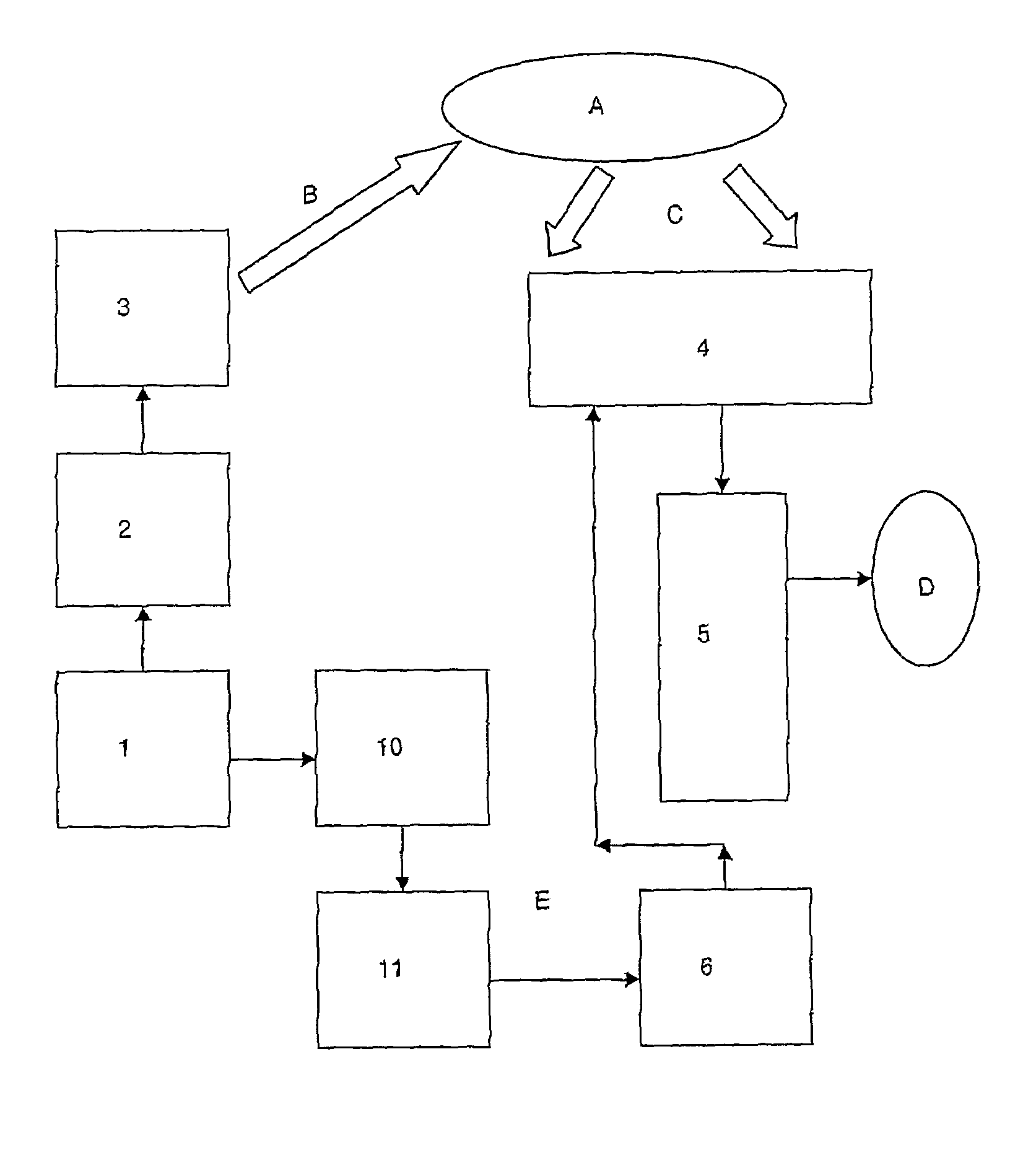
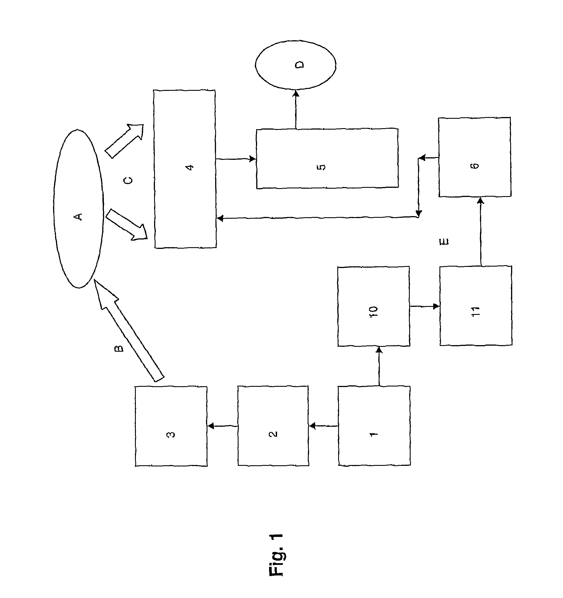
[0062]With reference to the described techniques and principles, it is the object of the present invention an integrated system (see FIG. 1) for locating fixed or moving objects A which are illuminated by a noisy waveform B, i.e. random and not predictable by an external observer, which, in the invention, is an interference (jammer) intended to either limit or prevent the operation of radars located aboard said objects.

[0063]Said waveform is emitted by a high power, broadband generator (in the aforesaid embodiment, such a generator is a radar jammer) in turn comprising a synthesizer 1, a power amplifier 2 and a transmitting antenna 3, preferably of high gain in the direction of the object, which is obtained by mechanically or electronically pointing the antenna beam towards the object itself.

[0064]The electromagnetic echo C, caused by the interaction of the waveform with the structure of the object and with its infrastructures, including the onboard radar antenna if present, is dete...

second embodiment

[0069]In the system of the invention, it is provided the use of pseudo-random waveforms, and the transmission of the reference signal E to the passive subsystem 4 is replaced by a simply reading of the next waveform to be transmitted by an appropriate storage element or device.

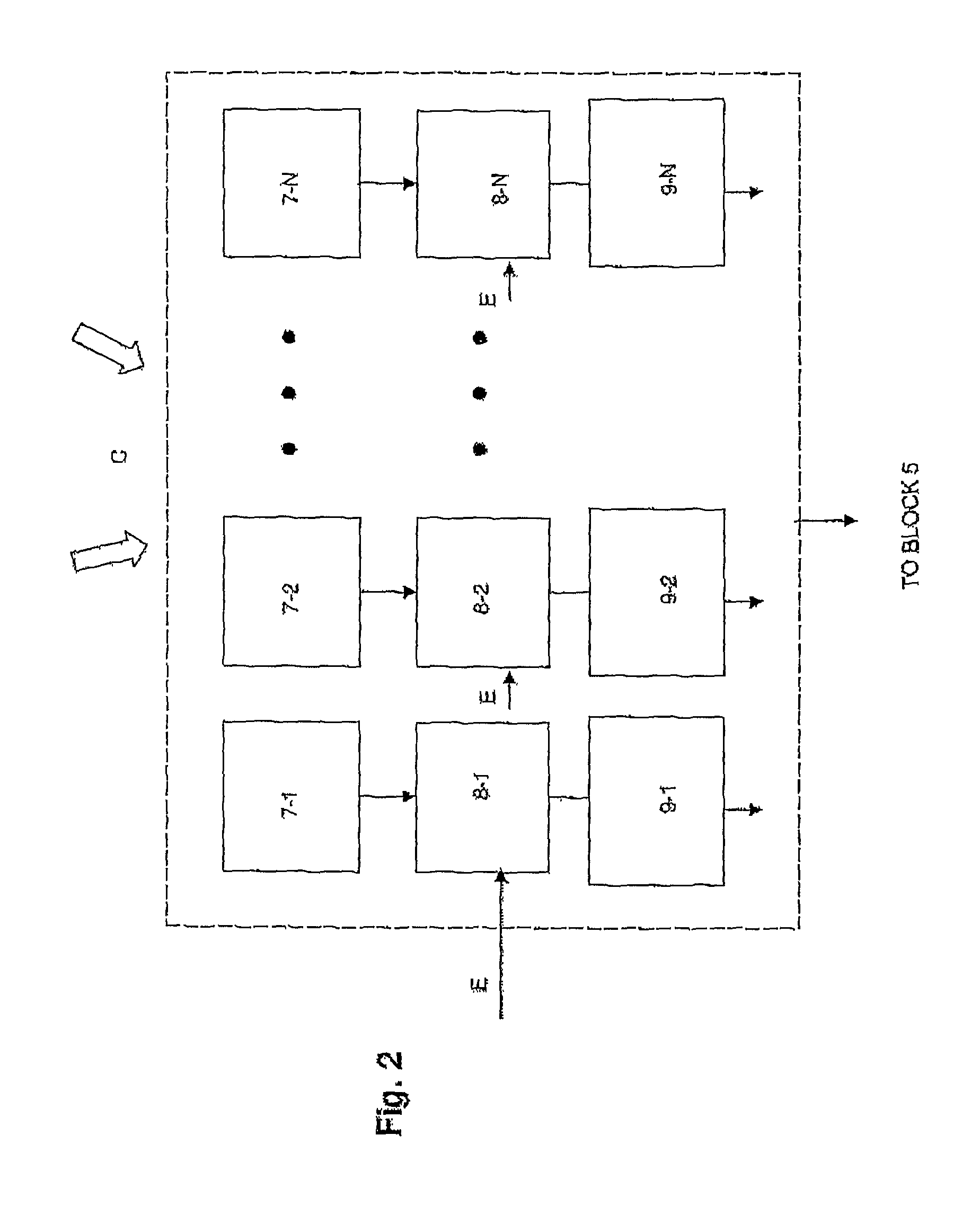
[0070]In this second embodiment, instead of by a radar jammer as shown in the first embodiment, the waveform is transmitted by a dedicated functional block, according to a diagram which provides for the replacement of blocks 6, 10 and 11 in FIG. 1 (transmitter 10, antenna 11 and antenna 6) with a direct connection of block 1, defining the synthesizer, to block 4, which defines the passive subsystem comprising the plurality of antenna-receiver sets.

[0071]The synthesizer 1, in this second embodiment, comprises in turn the blocks 12, 13 and 14 shown in FIG. 3.

[0072]The block 12, named “Waveforms storage” is a storage device, presently implementable by using techniques well known to persons skilled in the art, e.g...


PUM


Abstract

The present invention relates to a system for locating non-cooperating objects by means of a random or pseudo-random noisy type waveform generator, an amplifier, of said waveforms and an antenna which radiates them towards the object, which object generates an electromagnetic echo which is detected by a passive subsystem of antennas and receivers. The time delay and Doppler shift values are determined in the latter subsystem and in turn forwarded from encoding and modulating blocks to a central processor which estimates the position and the speed of the object. The passive subsystem receives, through a transmission channel or storage element, the reference signal which represents the transmitted noisy type waveform and uses it for calculating the bi-dimensional cross correlation (ambiguity function), which permits to estimate the time delay and the Doppler shift.

Description

FIELD OF THE INVENTION[0001]The invention is applied in the technical field of locating moving vehicles or objects (based on air, sea, land—the objects hereinafter are also named “targets”) for surveillance purposes. The location herein considered is of the non-cooperative type; i.e. it does not require the cooperation of the vehicle intended to be monitored: it is, indeed, based on electromagnetic wave back-scattering, particularly in the microwave region, on the body of the vehicle and on its onboard infrastructures, such as the antenna system (including the radar antenna) which equips many vehicles.[0002]From the two main parameters of the back-scattered electromagnetic signal, detected by one or more antennas, said parameters being the time delay and the frequency shift (Doppler effect), it is possible to obtain the parameters which allow us to reconstruct and estimate the motion of the object, i.e. its position and speed (in two or three dimensions, according to the type of mov...

Claims


Application Information

Patent Timeline
Patent Type & Authority Patents(United States)
IPC IPC(8): G01S7/38G01S13/42
CPCG01S13/003G01S13/0209G01S13/878G01S7/38
Inventor GALATI, GASPARE
Owner UNIVERSITY OF ROME TOR VERGATA
Why Eureka
Try Eureka