Adaptive synchronous rectification control method and apparatus

a rectification control and synchronous technology, applied in the field of synchronous rectification control, can solve the problems of additional pulses in the switching signal ssub>on /sub>and the stoppage of the switching signal, and achieve the effect of accurately measuring the detection signal

Active Publication Date: 2013-09-24
SEMICON COMPONENTS IND LLC
View PDF4 Cites 24 Cited by
  • Summary
  • Abstract
  • Description
  • Claims
  • Application Information

AI Technical Summary

Benefits of technology

[0010]In view of the disadvantages of prior arts, the main object of the present invention is to provide an apparatus and method for measuring the detection signal accurately by providing an adaptive synchronous rectification circuit.

Problems solved by technology

Hence, the first drawback of the prior art is that the switching signal SON will be stopped some periods temporarily during the valley voltage of the input voltage VIN once the threshold signal VT is set too high.
Hence, the second drawback of the prior art is that the additional pulse in the switching signal SON will be generated for each switching period once the threshold signal VT is set too low.

Method used


Image

  • Adaptive synchronous rectification control method and apparatus
  • Adaptive synchronous rectification control method and apparatus
  • Adaptive synchronous rectification control method and apparatus

Examples


Embodiment Construction

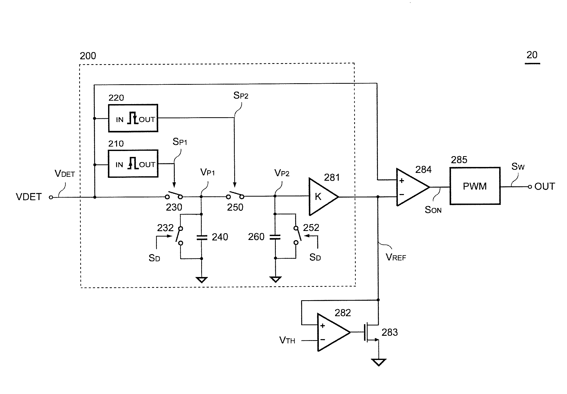
[0021]FIG. 3 shows a preferred embodiment of the control circuit 20 according to the present invention. The control circuit 20 includes an adaptive circuit 200, a clamped circuit formed by an operational amplifier 282 and a transistor 283, and a switching circuit including a comparator 284 and a PWM circuit 285. The adaptive circuit 200 is used to generate a reference signal VREF in response to the detection signal VDET of the power converter. The detection signal VDET is correlated to the input voltage VIN (as shown in FIG. 1) of the power converter. The adaptive circuit 200 comprises a rising edge detector 210, a falling edge detector 220, a sample-hold circuit and an amplifier 281. The sample-hold circuit is used for sampling and holding the detection signal VDET for generating the reference signal VREF. The sample-hold circuit is formed by a first sample switch 230, a first hold capacitor 240, a first discharge switch 232, a second sample switch 250, a second hold capacitor 260 ...


PUM


Abstract

An adaptive synchronous rectification control circuit and a control method are developed. The control circuit comprises an adaptive circuit that generates a reference signal in response to a detection signal of a power converter. A clamped circuit clamps the reference signal at a threshold voltage if the reference signal equals or is greater than the threshold voltage. A switching circuit generates a control signal to control a synchronous switch of the power converter in response to the detection signal and the reference signal. The control method generates the reference signal in response to the detection signal. The reference signal is clamped at the threshold voltage if the reference signal equals or is greater than the threshold voltage. The method further generates the control signal to control the synchronous switch of the power converter in response to the detection signal and the reference signal.

Description

REFERENCE TO RELATED APPLICATION[0001]This Application is being filed based on Provisional Patent Application Ser. No. 61 / 353,781 filed 11 Jun. 2010, currently pending.BACKGROUND OF THE INVENTION[0002]1. Filed of Invention[0003]The present invention relates to a synchronous rectification control, more particularly; relates to an adaptive synchronous rectification control at the secondary side of a transformer for improving efficiency and accuracy.[0004]2. Description of Related Art[0005]An offline power converter includes a power transformer to provide isolation from an AC line voltage to the output of the power converter for safety. In recent development, applying a synchronous rectifier in the secondary side of the power transformer is to achieve a high efficiency conversion for power converters. FIG. 1 shows a conventional power converter with the synchronous rectifier. The conventional power converter comprises a bridge rectifier 10 and a bulk capacitor CIN for converting a powe...

Claims


Application Information

Patent Timeline
Patent Type & Authority Patents(United States)
IPC IPC(8): H02H7/125H02M3/335
CPCH02M3/33592Y02B70/1475Y02B70/10
Inventor HSU, JHIH-DAYEH, CHIA-YOWANG, CHOU-SHENGSU, YING-CHIEHLU, RUI-HONG
Owner SEMICON COMPONENTS IND LLC
Why Eureka
Try Eureka