Solar photovoltaic inverters

a photovoltaic inverter and solar energy technology, applied in the direction of sustainable buildings, printed circuit aspects, electric apparatus casings/cabinets/drawers, etc., can solve the problems of microinverters adjacent to or on pv panels that bring other difficulties, reliability problems, special difficulties, etc., and achieve the effect of reducing the risk of water ingress through the cables

Active Publication Date: 2013-09-24
TESLA INC
View PDF30 Cites 81 Cited by
  • Summary
  • Abstract
  • Description
  • Claims
  • Application Information

AI Technical Summary

Benefits of technology

[0008]In embodiments the electrically conductive shield comprises a metal can having portions which fit opposite faces of the circuit board. In embodiments each portion has a flange which fits on, around or against a perimeter of the circuit board, so that the portions of the can clamp around the circuit board. The one or preferably more holes in the conductive shield (or can) enable the plastic, for example polyamide, overmould to be injection moulded over the combination of the circuit board and can. Thus the injection moulded plastic provides a sealed, solid plastic housing which encases the power conditioning circuit, the holes in the can enabling the plastic overmould to pass through the can to overmould the circuit board. The finished item is a robust, solid, sealed plastic unit, which is substantially free of air bubbles, and which provides a high degree of environmental protection. Furthermore the combined overmoulding and can arrangement facilitates the spreading and dissipation of heat from power components on the circuit board, helping to address the issues causing reliability problems.
[0010]In some implementations of the technique, dc input and / or ac output cables are overmoulded by injection moulding together with the shield and circuit board. This can help reduce the risk of water ingress through the cables. However an alternative approach, in embodiments preferable, is to replace in particular the dc cable or cables by a modular connector system in which a first interface part is mounted on the circuit board and then overmoulded to leave what is, in effect, a standard interface to the microinverter. Then any of a set of second mateable interface parts may be mated with this first interface part to connect to the photovoltaic panel or panels. This is advantageous because there is at present no universal standard for dc connection to a PV panel or module, and thus were the dc cable or cables to be overmoulded multiple different inverter versions would be needed to interface with multiple different types of PV panel. Instead the aforementioned approach enables a common manufacturing procedure followed by a customisation of the device to interface to a particular panel or panels.

Problems solved by technology

However, locating a microinverter adjacent to or on a PV panel brings other difficulties, in particular because such locations are subject to extreme temperature and environmental conditions including, for example, water, ice, humidity, and dry heat (depending upon the installation, up to or above 80° C.).
The very large temperature excursions, and in particular the extremes of high temperature which may be encountered, create particular difficulties.
Simple potting of the electronic components can in principle help to address some of these issues but in practice air bubbles and the like can give rise to local temperature hotspots (caused by the low thermal conductivity of air), which can lead to reliability problems and premature failure of the inverter.

Method used


Image

  • Solar photovoltaic inverters
  • Solar photovoltaic inverters
  • Solar photovoltaic inverters

Examples


Embodiment Construction

Power Conditioning Units

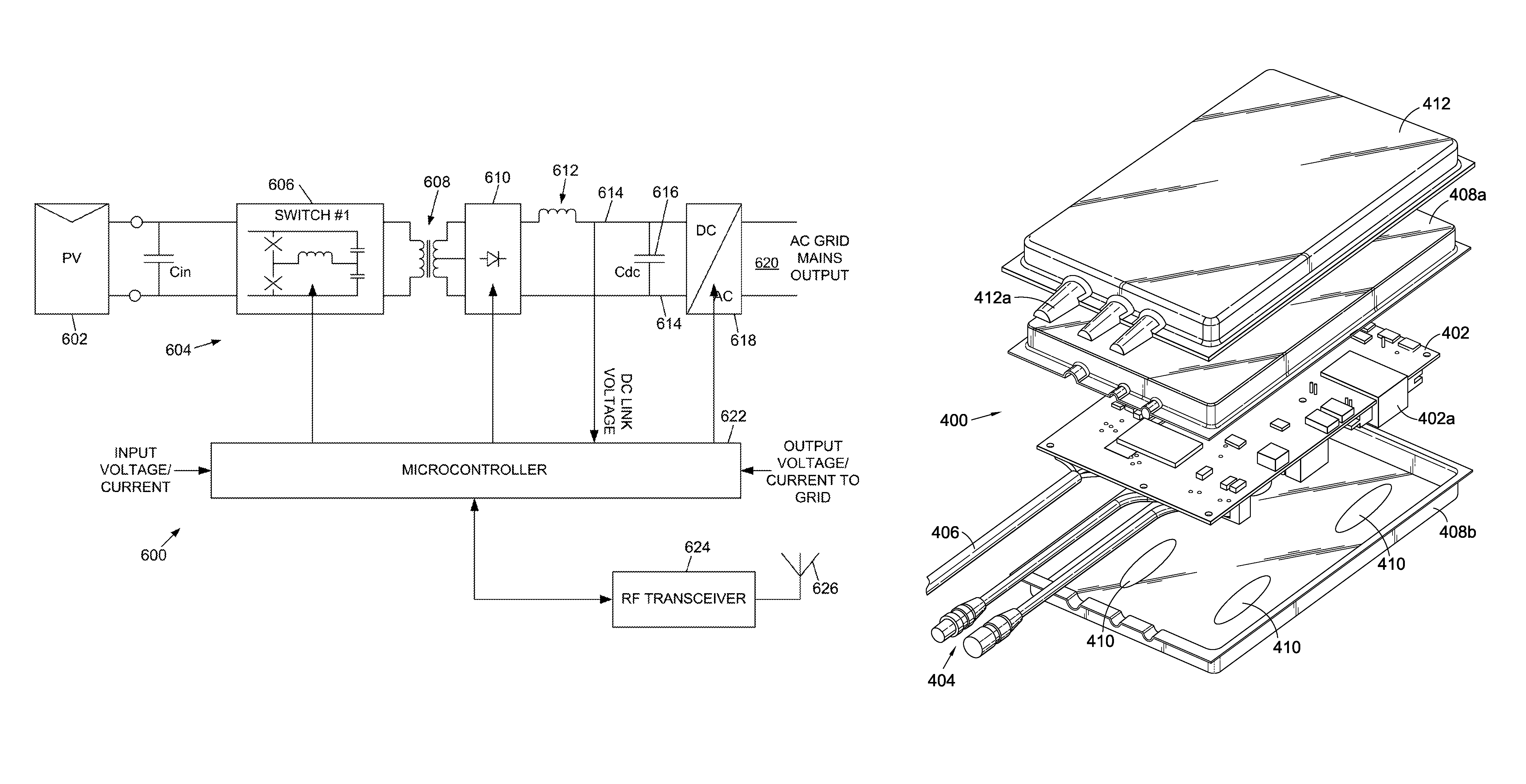
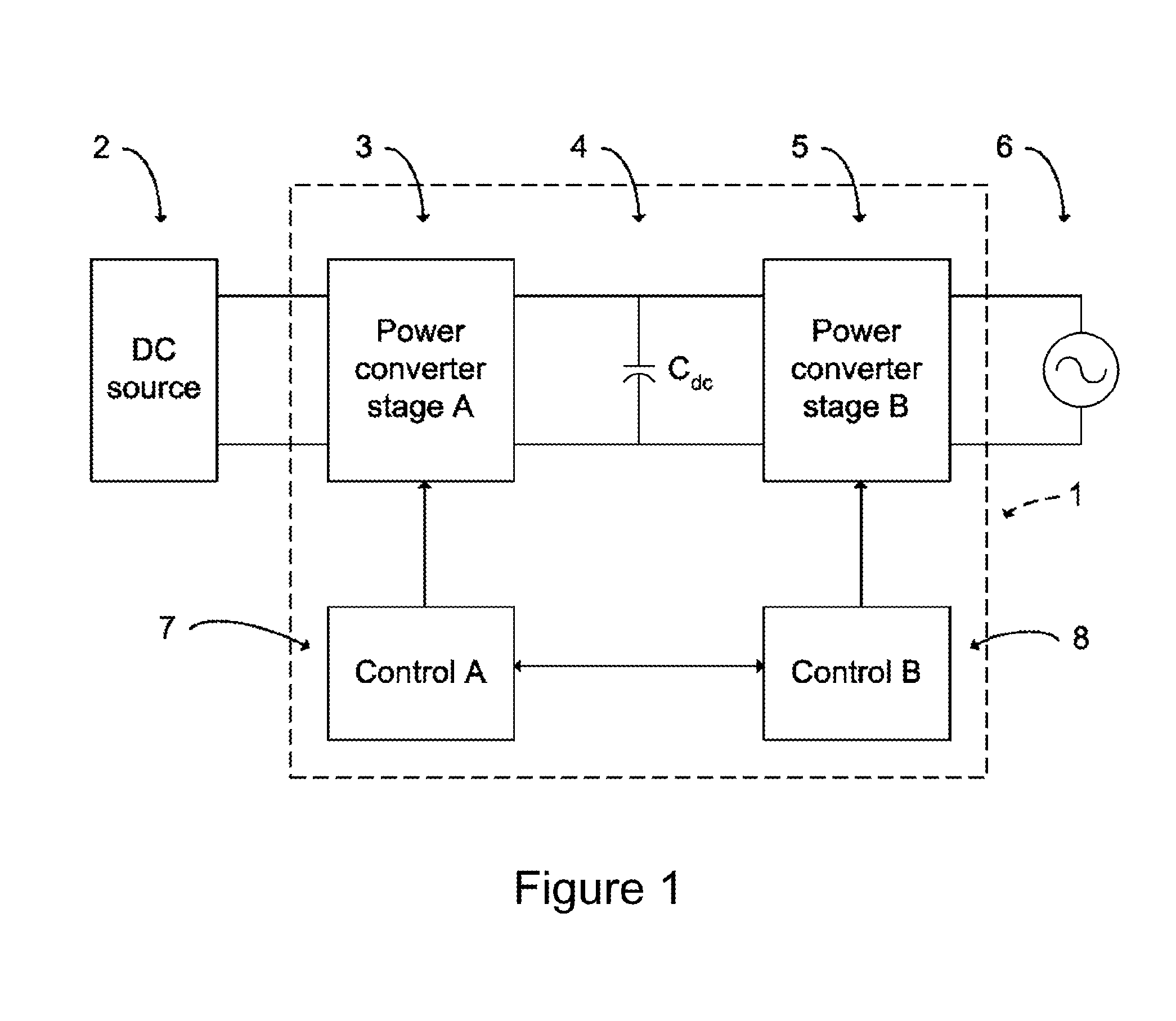
[0029]By way of background, we first describe an example photovoltaic power conditioning unit. Thus FIG. 1 shows photovoltaic power conditioning unit of the type we described in WO2007 / 080429. The power converter 1 is made of three major elements: a power converter stage A, 3, a reservoir (dc link) capacitor Cdc 4, and a power converter stage B, 5. The apparatus has an input connected to a direct current (dc) power source 2, such as a solar or photovoltaic panel array (which may comprise one or more dc sources connected in series and / or in parallel). The apparatus also has an output to the grid main electricity supply 6 so that the energy extracted from the dc source is transferred into the supply.

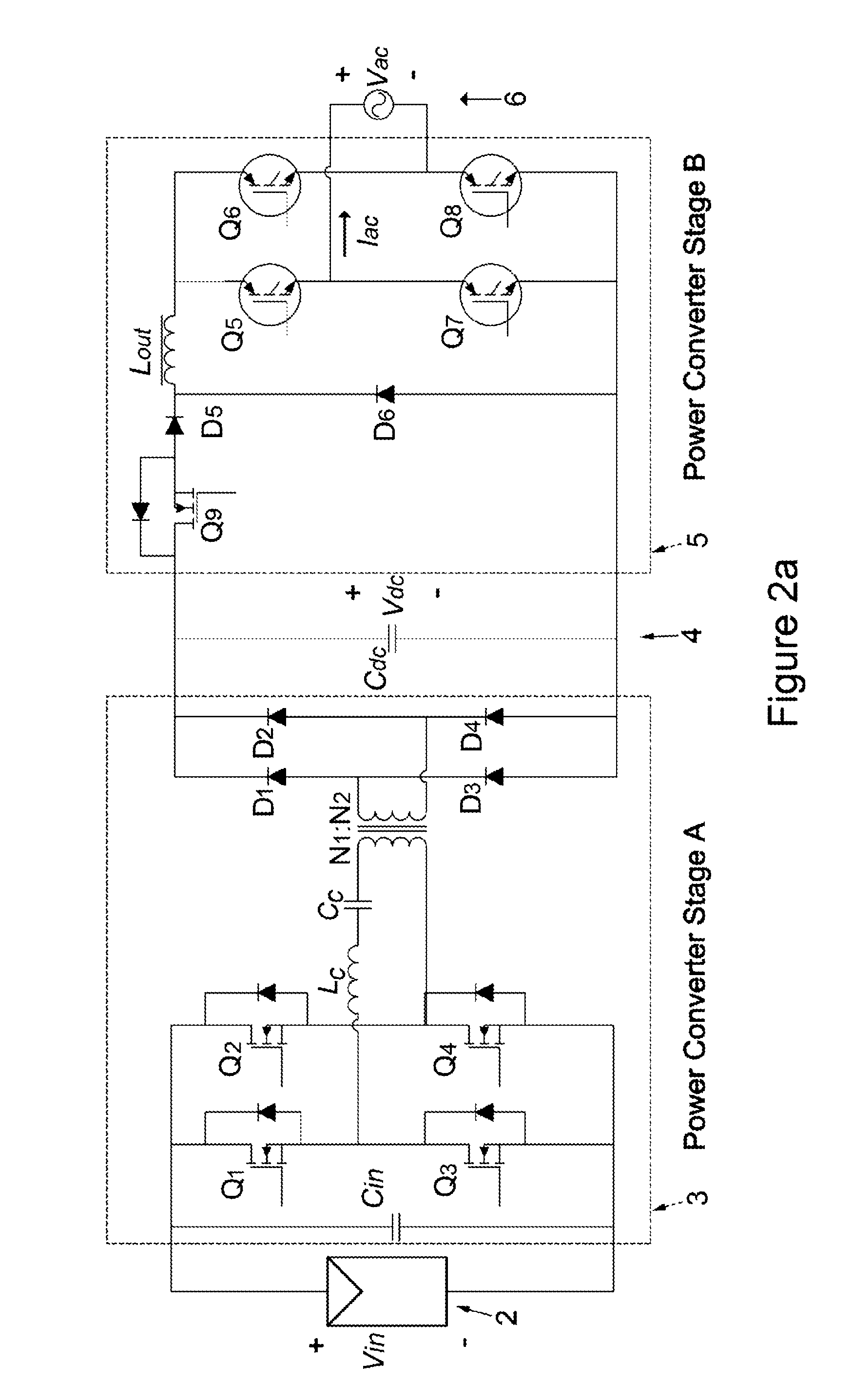
[0030]The power converter stage A may be, for example, a step-down converter, a step-up converter, or it may both amplify and attenuate the input voltage. In addition, it generally provides electrical isolation by means of a transformer or a coupled inductor. In gen...


PUM

PropertyMeasurementUnit
frequencyaaaaaaaaaa
peak-to-aaaaaaaaaa
peak-to-aaaaaaaaaa

Abstract

The invention relates to improved techniques for manufacturing power conditioning units (inverters) for use with photovoltaic (PV) modules, and to inverters manufactured by these techniques. We describe a solar photovoltaic inverter, comprising: a power conditioning circuit mounted on a circuit board, the power conditioning circuit having a dc power input to receive dc power from one or more photovoltaic panels and an ac power output to deliver ac power to an ac mains power supply; an electrically conductive shield enclosing said circuit board; and a plastic overmould over said conductive shield and said circuit board; wherein said electrically conductive shield has one or more holes to allow said plastic overmould to extend through said shield to cover said circuit board.

Description

CLAIM OF BENEFIT TO PRIOR APPLICATIONS[0001]This application claims benefit of an earlier-filed United Kingdom Patent Application 1104785.9, filed Mar. 22, 2011, which is incorporated herein by reference.FIELD OF THE INVENTION[0002]This invention relates to power conditioning units (inverters) for use with photovoltaic (PV) modules for delivering ac power either directly to the mains (grid) utility supply or for powering mains (grid) devices directly, independently from the mains utility supply. More particularly the invention relates to improved techniques for manufacturing such inverters, and to inverters manufactured by these techniques.BACKGROUND TO THE INVENTION[0003]We have previously described a range of improved techniques for increasing reliability and efficiency in photovoltaic inverters (see, for example, WO2007 / 080429 and others of our published patent applications).[0004]We now particularly address problems which can arise with so-called microinverters. A microinverter ...

Claims


Application Information

Patent Timeline
Patent Type & Authority Patents(United States)
IPC IPC(8): H02M7/537H05K9/00
CPCH02M3/338H02S40/32H02J3/383H02M2001/007H05K3/284Y10T29/4913H05K2201/10371H05K2203/1316Y02E10/563H05K2201/10166H02J2300/24H02J3/381Y02E10/56H02M1/007H05K5/0034H05K5/0247H05K5/064Y02B10/10
Inventor GARRITY, PAUL
Owner TESLA INC
Why Eureka
Try Eureka