
Vehicle air conditioner

a technology for air conditioners and vehicles, applied in the field of vehicles, can solve the problems of reducing fuel economy, reducing the efficiency of vehicles, and reducing the maintenance cost of vehicles, so as to maximize the overall vehicle performance, and improve the effect of maintainability

Inactive Publication Date: 2013-10-01
OMNITHERM +1
View PDF10 Cites 3 Cited by
  • Summary
  • Abstract
  • Description
  • Claims
  • Application Information

AI Technical Summary

Benefits of technology

The system enhances fuel economy, reduces maintenance time and labor, minimizes refrigerant usage and leakage risks, and improves high-ambient temperature performance while providing efficient climate control with fewer penetrations through the vehicle hull, thus addressing the trade-offs between personnel protection and fuel economy.

Problems solved by technology

Increase the amount of armor on a vehicle to improve personnel protection and you increase the weight of the vehicle and you decrease its fuel economy.
Increase a vehicles' fuel economy by reducing its engine's horsepower and you degrade its performance and decrease a soldier's ability to get out of harms way.
While these are the most obvious components of the conundrum, several other issues emerge upon further inspection.
The heating and / or cooling, depending on the outside ambient temperature, reduce the vehicles fuel economy.
This reduction in economy is a result of not only the horsepower required for its operation but also the weight that its components add to the vehicle.
Optimizing vehicle systems such as cabin climate control cannot be done without a “Total Vehicle” approach.
This process adds time and labor to the process.
This creates three problems in the Modern Military Vehicle.
The longer the refrigerant line, the higher the risk of leakage.
When the system is down it takes costly time and labor to repair.
Finally, each penetration that is bored into the hull of the vehicle increases the danger to the cabin crew by providing a path for foreign objects or materials to enter.
Another issue with a conventional air conditioning system is that the compressor speed is directly proportional to the speed of the engine.
This means that the compressor must operate in either an “off” or “on” mode to control temperature thereby reducing the efficiency of the compressor.

Method used


Image

  • Vehicle air conditioner
  • Vehicle air conditioner
  • Vehicle air conditioner

Examples


Embodiment Construction

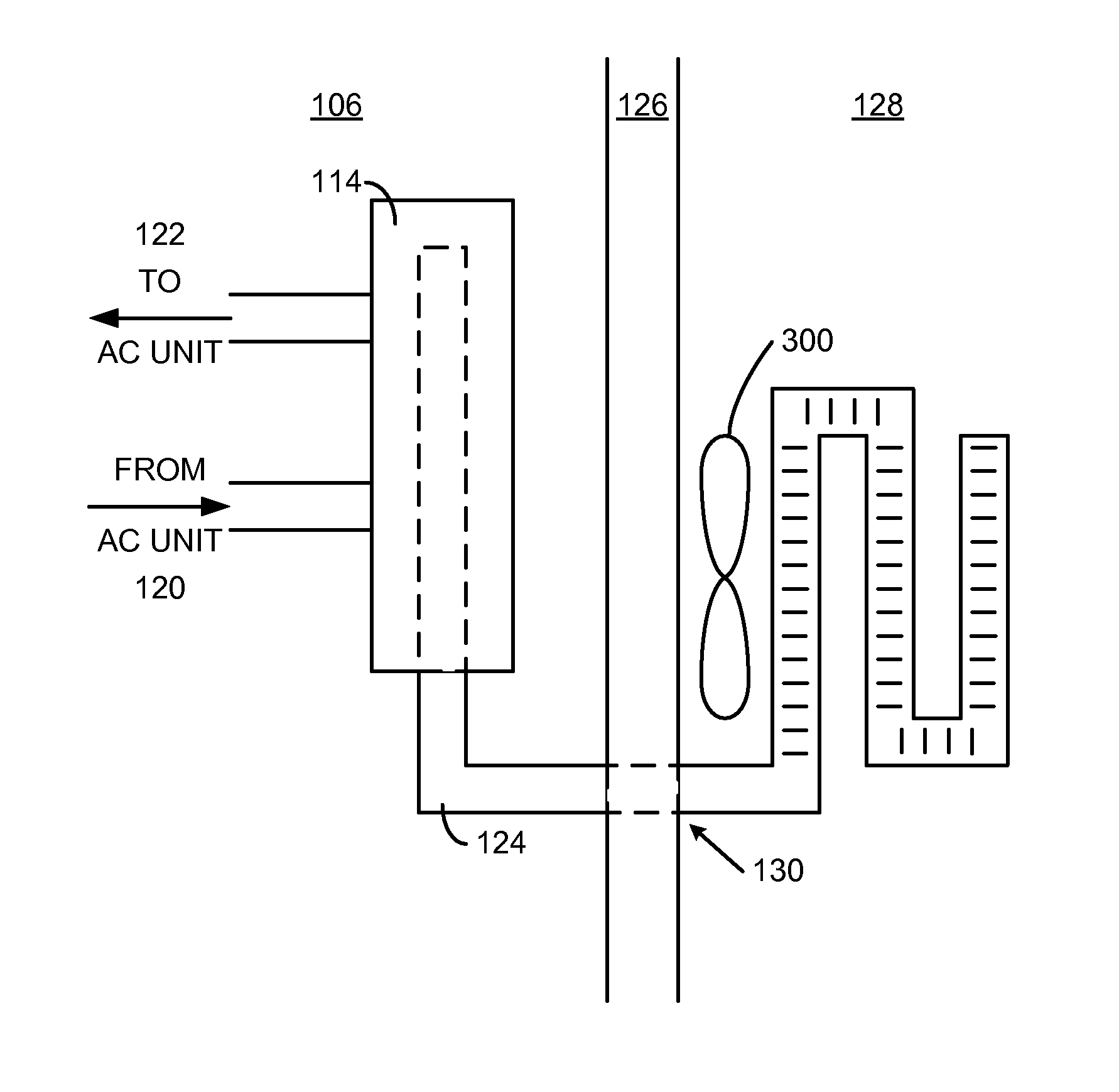
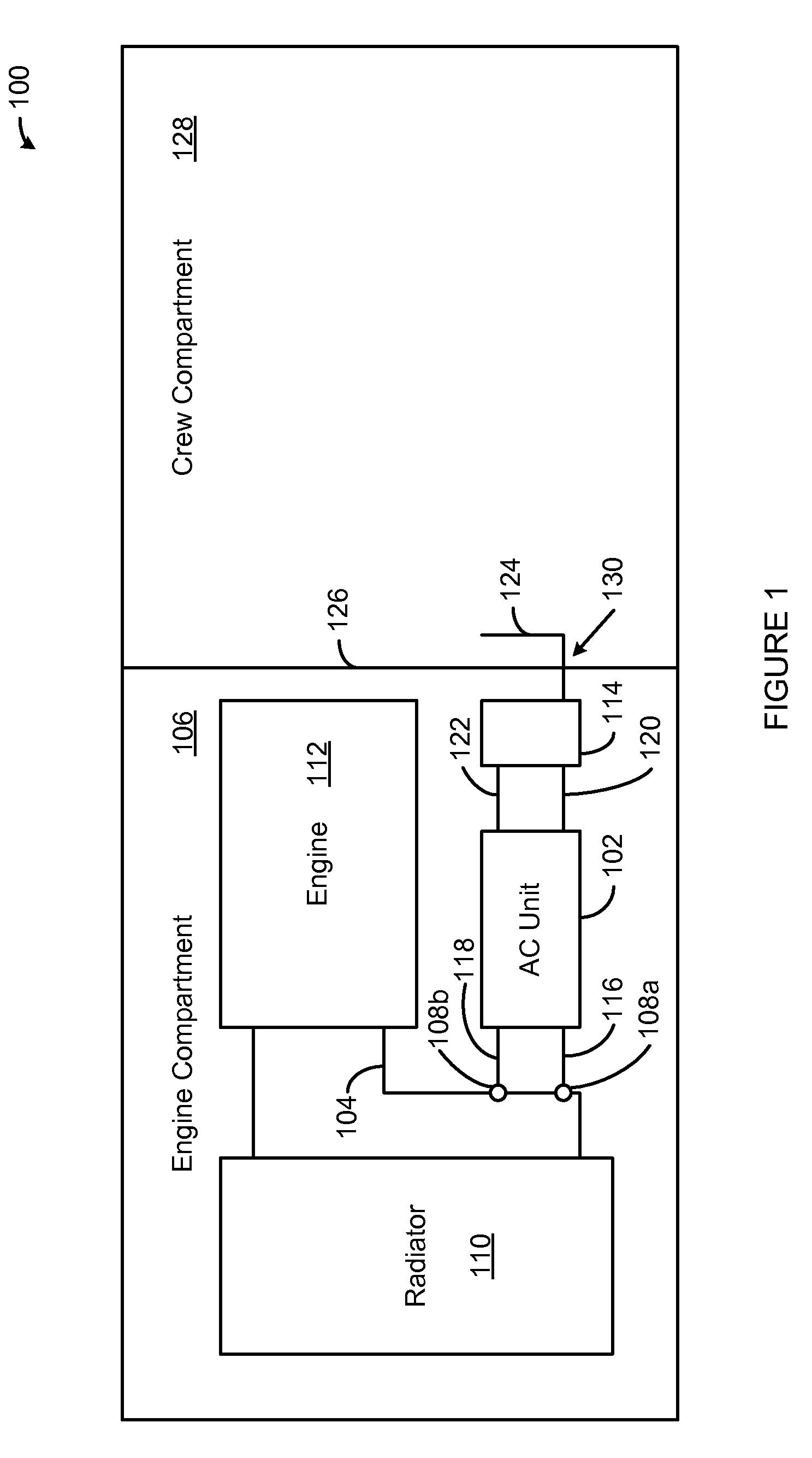
[0029]While the making and using of various embodiments of the present invention are discussed in detail below, it should be appreciated that the present invention provides many applicable inventive concepts that can be embodied in a wide variety of specific contexts. The specific embodiments discussed herein are merely illustrative of specific ways to make and use the invention and do not delimit the scope of the invention. The discussion herein relates primarily to a modular air conditioning system, such as the OmniTherm AC-200, but it will be understood that the concepts of the present invention are applicable to non-military vehicles, such as commercial vehicles.

[0030]The present invention provides an air conditioning system that, among other things, is more efficient and easy to install or remove than conventional air conditioning systems. The present invention utilizes existing vehicle subsystems such as the engine coolant and on-board electrical or hydraulic systems to maximi...


PUM


Abstract

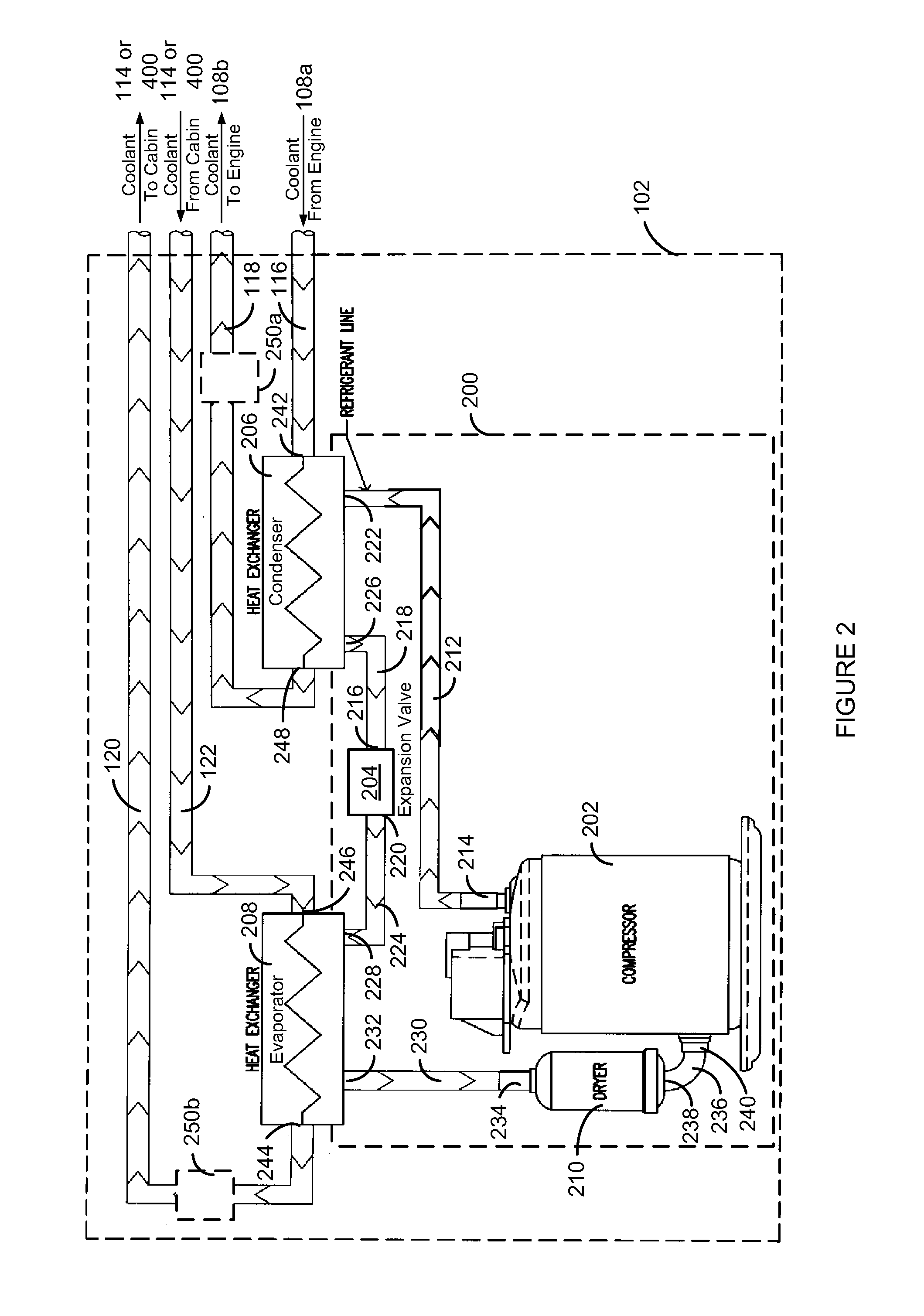
The present invention provides an air conditioner for a vehicle that includes a closed refrigeration loop. The closed refrigeration loop includes a compressor, a refrigerant-to-coolant heat exchanger, a coolant-to-refrigerant heat exchanger and a refrigerant dryer in series fluid connection with one another. An engine coolant outlet connector is connected to the coolant-to-refrigerant exchanger. A compartment inlet connector connected to the coolant-to-refrigerant heat exchanger. A compartment outlet connector connected to the refrigerant-to-coolant heat exchanger. An engine coolant inlet connector connected to the refrigerant-to-coolant heat exchanger.

Description

FIELD OF THE INVENTION[0001]The present invention relates generally to the field of vehicles and, more particularly, to an air conditioner for vehicles.BACKGROUND OF THE INVENTION[0002]The modern battlefield requires new and innovative tactical vehicle technologies to address challenges whose emergence has been seen with dramatic effect in both Iraq and Afghanistan. Among these, personnel protection and fuel economy ranks at the top of the list.[0003]In many ways personnel protection and fuel economy go hand-in-hand. Increase the amount of armor on a vehicle to improve personnel protection and you increase the weight of the vehicle and you decrease its fuel economy. Increase a vehicles' fuel economy by reducing its engine's horsepower and you degrade its performance and decrease a soldier's ability to get out of harms way. While these are the most obvious components of the conundrum, several other issues emerge upon further inspection. For example, completely armoring a vehicle now ...

Claims


Application Information

Patent Timeline
Patent Type & Authority Patents(United States)
IPC IPC(8): F25D17/02B60H1/32
CPCB60H1/00357B60H1/00414B60H1/00542F25B29/003F25B2327/001B60H1/32284
Inventor MASTERS, W. JAMESFUGATE, DOUGLAS W.WILSON, EDWIN E.JOHNSON, JOHN T.MASTERS, W. JASON
Owner OMNITHERM
Learn More