
Ultrasonic compliance zone system

a technology of compliance zone and ultrasonic sound, applied in the direction of electrical signalling details, mechanical actuation of burglar alarms, instruments, etc., can solve the problems of difficult enforcement of even simple protocols, difficult real-time enforcement, and difficult enforcement of hand hygiene protocols

Active Publication Date: 2013-10-01
THE GENERAL HOSPITAL CORP
View PDF39 Cites 24 Cited by
  • Summary
  • Abstract
  • Description
  • Claims
  • Application Information

AI Technical Summary

Benefits of technology

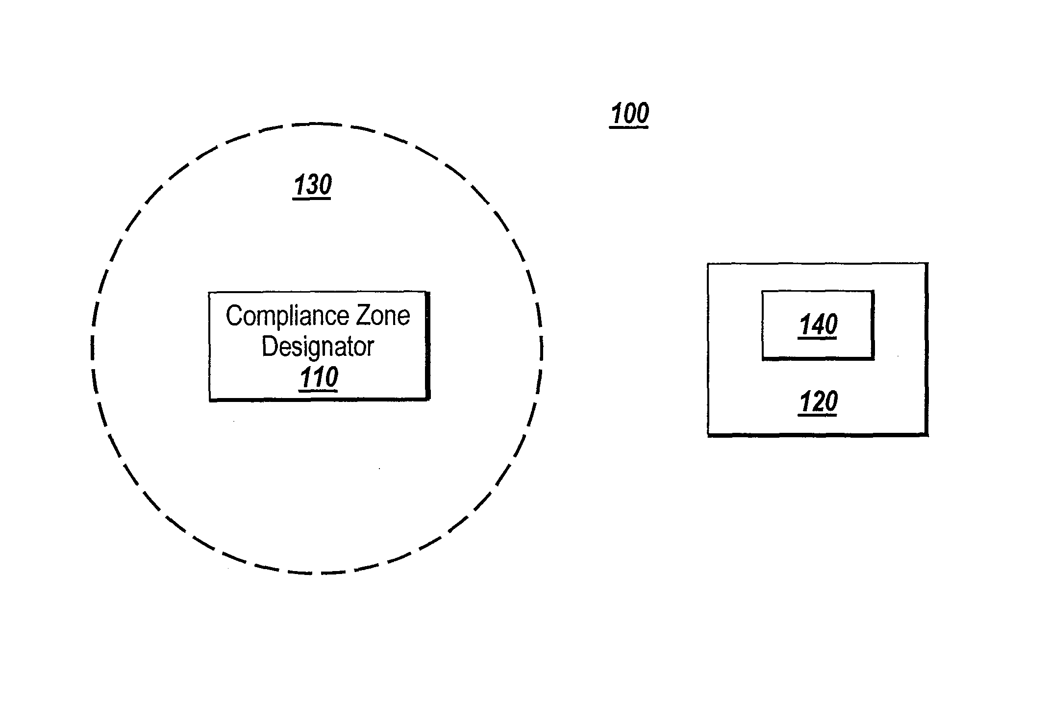
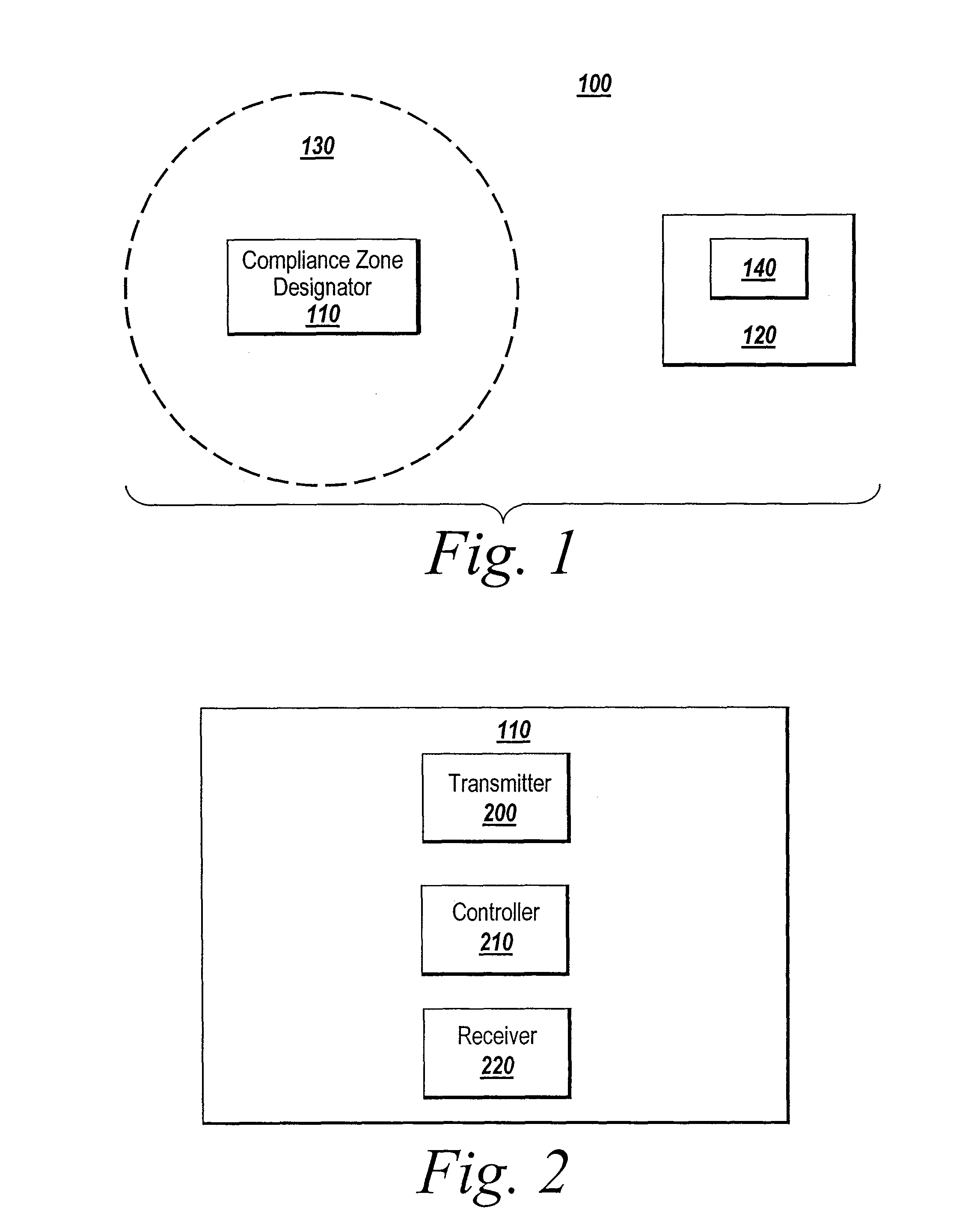
The patent discusses the use of ultrasound to establish zones and the benefits of this method over other technologies, such as infrared and radio frequency. It also describes a system that uses a dual compliance zone designator to create two zones within a single room. A wearable device can determine which zone it occupies by computing the travel time from the opposing transmitters. The technical effects of this invention include reliable communication and well-defined zones regardless of topography, as well as the ability to encode and decode data in ultrasound signals.

Problems solved by technology

In factories, these compliance zones may be hazardous zones where dangerous equipment or chemicals are used, and that only qualified personnel with appropriate safety gear are allowed to access.
Enforcement of even simple protocols may be difficult when dealing with a large and busy facility like a hospital, and real time enforcement may be extremely difficult.
However, enforcement of the behaviors specified in hand hygiene protocols can be difficult in a hospital due to the large number of individuals requiring monitoring and the generally busy fast-paced environment inside a hospital.
However, there are significant drawbacks to conventional techniques of establishing zones with the transmission of infrared signals.
Generally, conventional systems do not work if the line-of-sight between an infrared transmitter and an infrared receiver is blocked, e.g. if a receiver badge worn by a clinician is covered by the clinician's clothing or the protective garb that is required to be worn in certain patient rooms.
This often requires uncomfortable or undesirable placement of the badges, e.g. at the back of the neck or shoulder.
Exposure of the badges outside the clothing also breaches the infection control barrier of the clothing, which makes the infrared receiver badges unsuitable for use in clean areas.
For similar reasons, infrared transmitters that indicate use of a hand-washing station cannot be integrated into a hand-washing dispenser because the infrared signals do not penetrate the dispenser casing.
Infrared signals are also susceptible to shadowing, which occurs when an obstacle obscures the main signal path between the infrared transmitter and receiver.
These conventional techniques are expensive to install and require an extensive infrastructure.
However, this non-line-of-sight characteristic also means that the radio frequency signals can penetrate walls, and cannot reliably be contained within zones that are defined between a set of walls.
Thus, in these conventional systems, a radio frequency receiver may have difficulty in identifying the source of a received signal.
This is because ultrasound signals are typically not suited to sending large amounts of data.
In addition, ultrasound signals are often prone to multipath interference, a phenomenon whereby a wave from a source travels to a detector via two or more paths and, under the right conditions, the two or more components of the wave interfere.
Furthermore, in view of the drawbacks of using infrared and radio frequency signal transmissions in establishing zones and despite the conventional view that ultrasound is not appropriate for data transmission, the system provided by exemplary embodiments uses ultrasound transmissions to establish zones.

Method used


Image

  • Ultrasonic compliance zone system
  • Ultrasonic compliance zone system
  • Ultrasonic compliance zone system

Examples


example featuring

VII. Hospital Example Featuring Timeout Protocol

[0146]Another exemplary use of the system in accordance with the present invention is in recording and enforcing a timeout protocol in an operating room before the beginning of a surgical procedure. During a timeout protocol, good practice dictates that all hospital staff participating in the surgical procedure (e.g. surgeons, nurses, anesthetists, etc.) pause to make sure that the correct patient is about to get the correct surgical procedure. During a timeout protocol, a staff-member announces the start of the protocol and reads aloud the patient's name and details of the surgical procedure. The timeout protocol prevents avoidable surgical errors by allowing a hospital staff-member to speak up if he / she does not agree on the patient's identity or on the details of the surgical procedure. Timeout protocols are difficult to enforce in practice, as staff-members often continue to work during the protocol and fail to pay attention to the...


PUM


Abstract

A system is provided for establishing a compliance zone and monitoring interactions therewith. The system includes a compliance zone designator and a wearable device. The compliance zone designator transmits an ultrasound signal to establish the compliance zone. The ultrasound signal may be encoded with information on the compliance zone. The compliance zone designator is configured for placement at a location in which the compliance zone is desired. The wearable device is separate from the compliance zone designator. The wearable device includes a compliance zone recognition component configured to recognize the compliance zone and identify one or more pre-defined interaction criteria for the compliance zone. When the wearable device is within the compliance zone, the compliance zone recognition component recognizes the compliance zone and identifies the interaction criteria of the compliance zone. Based on the interaction criteria the wearable device determines and records compliance with the interaction criteria. The recorded data is optionally used to set off real-time alerts. The recorded data is also optionally used in subsequent analysis and documentation of compliance with protocols.

Description

RELATED APPLICATIONS[0001]This application is a continuation-in-part of U.S. application Ser. No. 12 / 487,366, filed on Jun. 18, 2009, now issued as U.S. Pat. No. 8,164,439 on Apr. 24, 2012, and entitled “Ultrasonic Compliance Zone System,” which application is incorporated herein by reference.FIELD OF THE INVENTION[0002]Exemplary embodiments of the present invention relate to monitoring and enforcing protocols in facilities. More specifically, exemplary embodiments relate to establishing designated compliance zones through transmission of data using ultrasound signals, and monitoring interactions with the designated compliance zones to determine compliance with protocols.BACKGROUND OF THE INVENTION[0003]Many facilities have protocols in place to comply with health, safety, insurance, and regulatory requirements. In large facilities, such as factories and hospitals, there may be a large number of people, equipment, areas, and other resources that need to be tracked in the enforcement...

Claims


Application Information

Patent Timeline
IPC IPC(8): G08B1/08G08B23/00H04B1/02
CPCG08B13/1627G08B21/22G08B21/245G08B13/1618
Inventor DEMPSEY, MICHAELNEWBOWER, RONALD S.
Owner THE GENERAL HOSPITAL CORP
Learn More