
Mask assembly for thin film deposition of flat panel display

a technology of mask assembly and flat panel display, which is applied in the direction of vacuum evaporation coating, solid-state devices, coatings, etc., can solve the problems of increasing the error of mask assembly and substrate array, difficult alignment of division mask and mask frame, etc., and achieve the effect of preventing the generation of pattern position error at the pattern opening of division mask

Active Publication Date: 2013-10-08
SAMSUNG DISPLAY CO LTD
View PDF17 Cites 9 Cited by
  • Summary
  • Abstract
  • Description
  • Claims
  • Application Information

AI Technical Summary

Benefits of technology

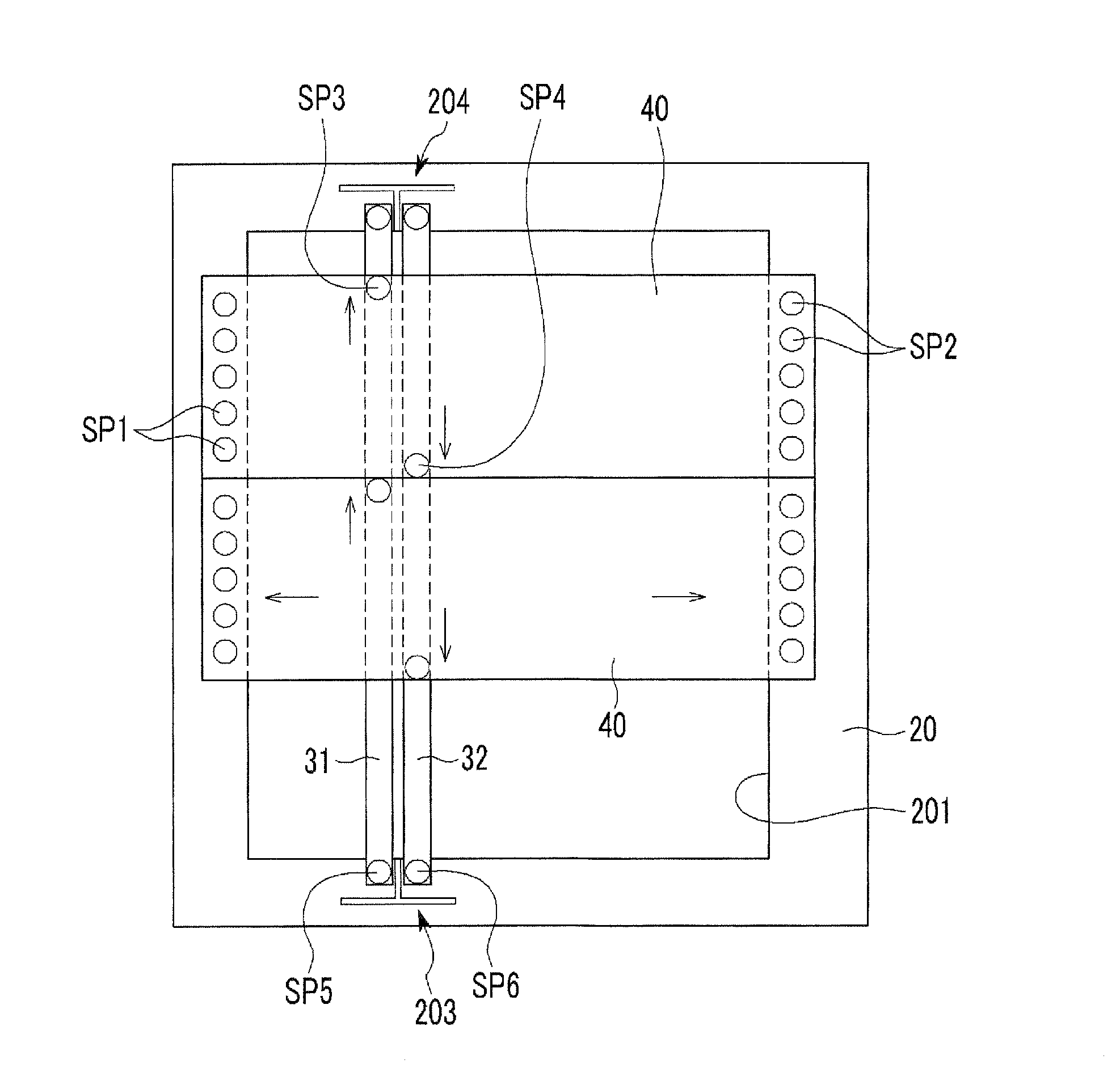
The patent text describes a method to correct distortion in a division mask used in semiconductor manufacturing equipment. The method involves using first and second change compensating members to adjust the mask form in both the length and width directions. By applying tension to the mask in both directions, the mask's form is corrected even if the frame it is attached to is distorted. This prevents position errors in the pattern of the semiconductor device being manufactured.

Problems solved by technology

Hence, the division mask is increased to remain behind because of gravity, and it becomes difficult to align the division mask and the mask frame, and the mask assembly and the substrate array.
The form distortion of the mask assembly generates a position error of the pattern from the pattern opening of the division mask, and further increases the error.

Method used


Image

  • Mask assembly for thin film deposition of flat panel display
  • Mask assembly for thin film deposition of flat panel display
  • Mask assembly for thin film deposition of flat panel display

Examples


Embodiment Construction

[0029]The exemplary embodiments will be described more fully hereinafter with reference to the accompanying drawings, in which exemplary embodiments are shown. As those skilled in the art would realize, the described embodiments may be modified in various different ways, all without departing from the spirit or scope of the present invention.

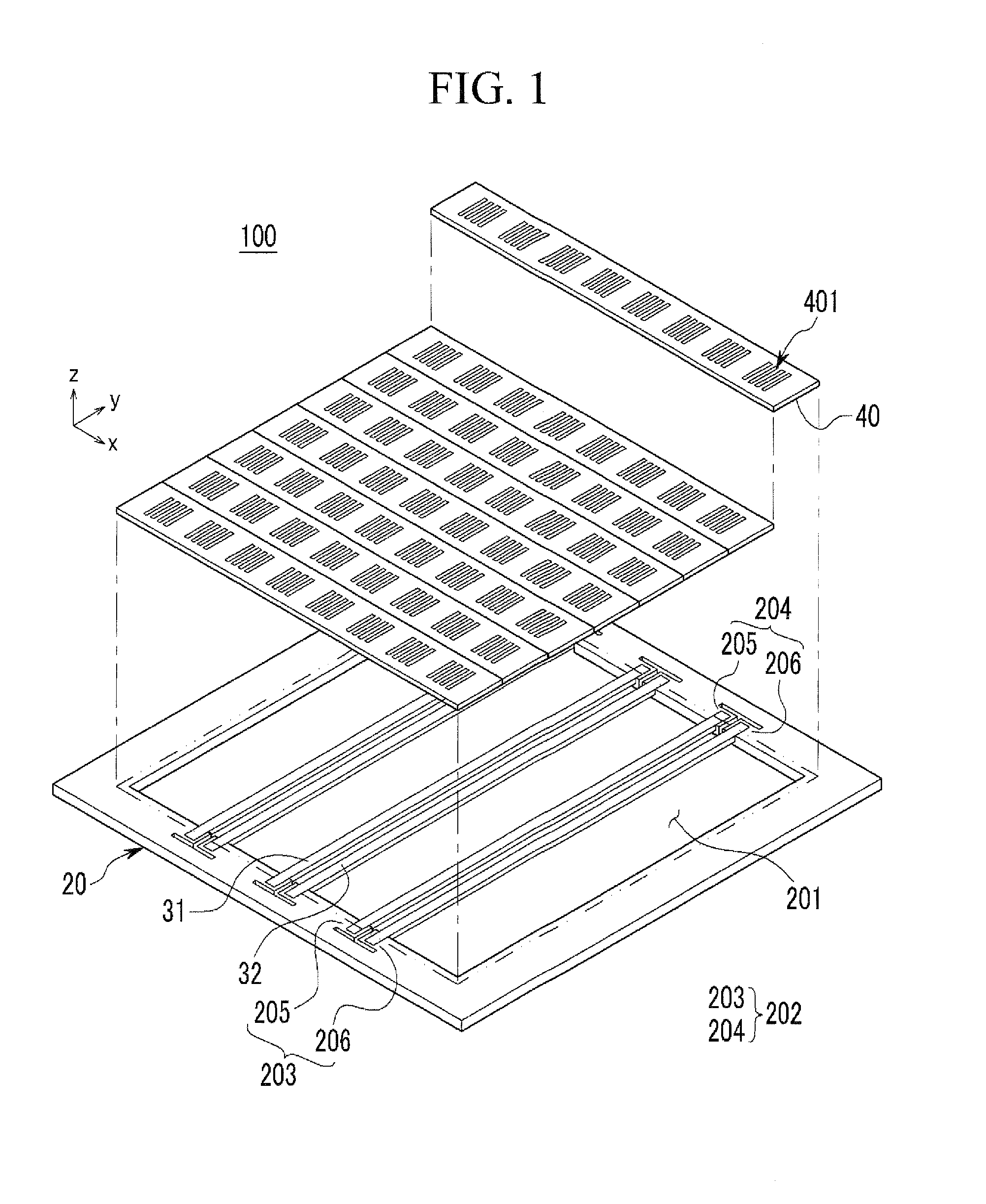
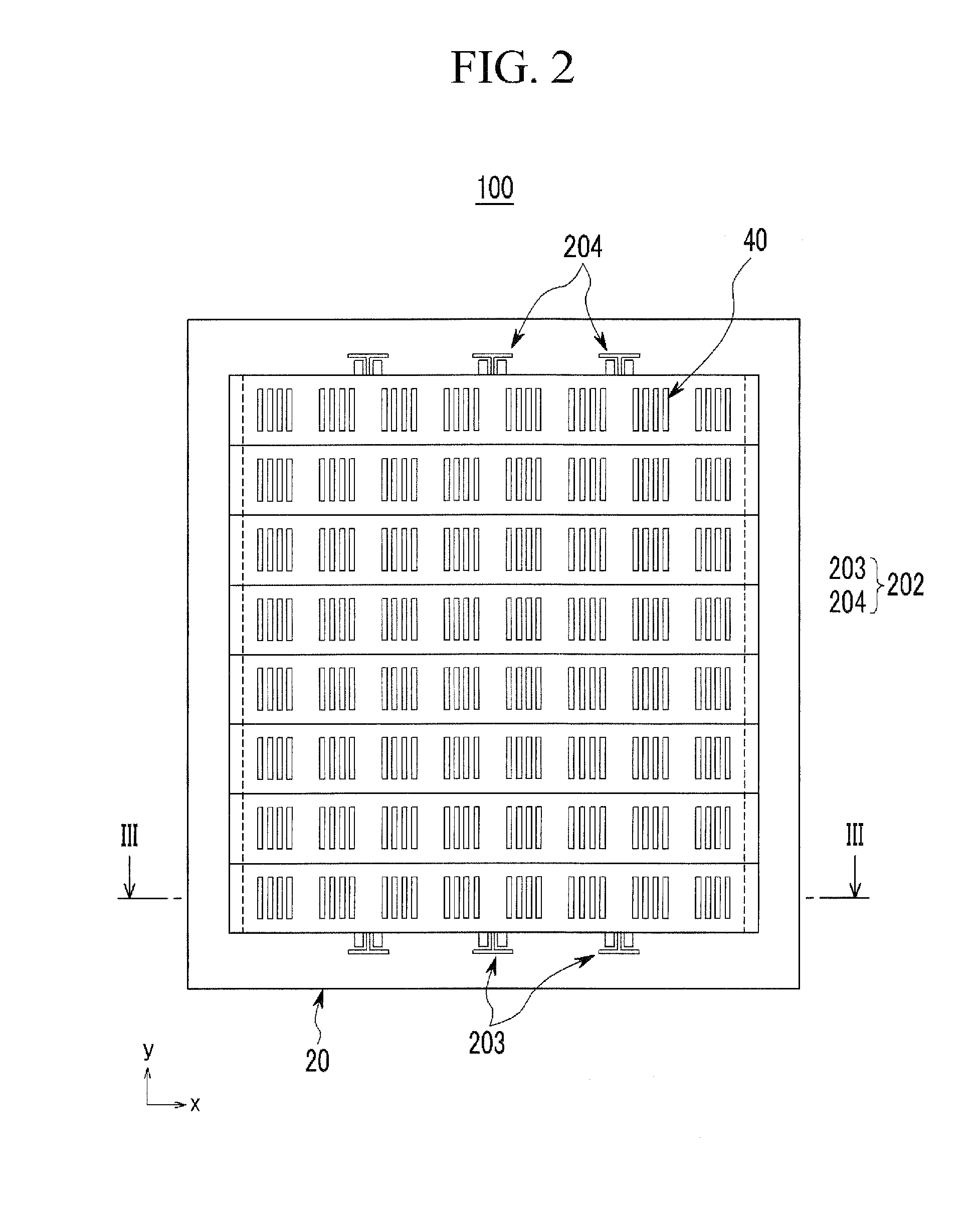
[0030]FIG. 1 shows an exploded perspective view of a thin-film deposition mask assembly of a flat panel display according to a first exemplary embodiment, FIG. 2 shows a top plan view of a thin-film deposition mask assembly of a flat panel display shown in FIG. 1, and FIG. 3 shows a cross-sectional view with respect to a line III-III shown in FIG. 2.

[0031]Referring to FIG. 1 to FIG. 3, the thin-film deposition mask assembly 100 (for convenience, mask assembly) of a flat panel display according to the first exemplary embodiment includes a frame 20 having a penetrated opening 201, at least one pair of a first change compensating member and a secon...


PUM

PropertyMeasurementUnit
tensionaaaaaaaaaa
lengthaaaaaaaaaa
widthaaaaaaaaaa

Abstract

A described technology relates generally to a thin-film deposition mask assembly of a flat panel display for correcting form distortion caused by tension of a division mask. The thin-film deposition mask assembly includes: a frame for forming a penetrated opening; a first change compensating member and a second change compensating member disposed across the opening, fixed to a free end member formed by partially cutting the frame from the opening, and arranged as a pair; and a plurality of division masks being disposed to cross the first change compensating member and the second change compensating member on top sides of the first change compensating member and the second change compensating member.

Description

RELATED APPLICATIONS[0001]This application claims priority to and the benefit of Korean Patent Application No. 10-2009-0126210 filed in the Korean Intellectual Property Office on Dec. 17, 2009, the entire contents of which are incorporated herein by reference.BACKGROUND OF THE INVENTION[0002]1. Field of the Invention[0003]The described technology relates generally to a thin-film deposition mask assembly of a flat panel display. More particularly, the described technology relates generally to a thin-film deposition mask assembly of a flat panel display for attaching a division mask in a mask frame.[0004]2. Description of the Related Art[0005]Conventionally, flat panel displays include organic light emitting displays, liquid crystal displays (LCD), and plasma display panels (PDP). Manufacturing of an organic light emitting diode (OLED) display includes a process for forming an electrode and an organic emission layer with a thin film of a specific pattern. A mask assembly is used for t...

Claims


Application Information

Patent Timeline
Patent Type & Authority Patents(United States)
IPC IPC(8): B05C11/11B05D5/00
CPCC23C14/042H01L51/0011H10K71/166C23C14/046
Inventor PARK, JAE-SEOK
Owner SAMSUNG DISPLAY CO LTD
Learn More