
Electromagnetic energy assisted drilling system and method

a technology of electromagnetic energy and drilling system, applied in the direction of cutting machine, fluid removal, insulation, etc., can solve the problems of weakening the rock, less than optimal, and inability to apply these machines and techniques to hard rock such as granite and basal

Inactive Publication Date: 2013-10-08
MCGILL UNIV
View PDF15 Cites 6 Cited by
  • Summary
  • Abstract
  • Description
  • Claims
  • Application Information

AI Technical Summary

Benefits of technology

The present invention provides a drill bit that uses microwaves to penetrate material. The drill bit has a cutting tool and a microwave antenna that irradiates the material with the microwaves before the material is removed by the cutting tool. The invention also provides a system and method to thermally treat selected materials in an aggregate, which involves subjecting the material to specific frequencies of electromagnetic radiation that induce fractures in the material. The technical effects include improved drilling efficiency and the ability to treat materials without damaging the surrounding matrix.

Problems solved by technology

One drawback of these prior art machines is that they are designed primarily for working relatively soft rock formations and as a result, application of these machines and techniques to hard rock such as granite and basalt is either not possible or inefficient due to slow speed and increased tool wear.
These prior art methods and devices reveal the use of a variety of thermal sources such as gas jets, lasers and radiant electric heaters and the like, but have proven less than optimal due to their limited effect, large expense and additional time required.
The prior art also reveals thermally treating rock formations using microwaves in order to introduce thermal expansion causing tensile stress thereby fracturing and weakening the rock so that it is more susceptible to subsequent excavation by mechanical mining machines.
One drawback of these prior art methods is that, as the microwaves are not optimised in order to maximise the effect of thermal expansion weakening of the rock is reduced, or alternatively high power microwave sources must be used thereby reducing efficiency.

Method used


Image

  • Electromagnetic energy assisted drilling system and method
  • Electromagnetic energy assisted drilling system and method
  • Electromagnetic energy assisted drilling system and method

Examples


Embodiment Construction

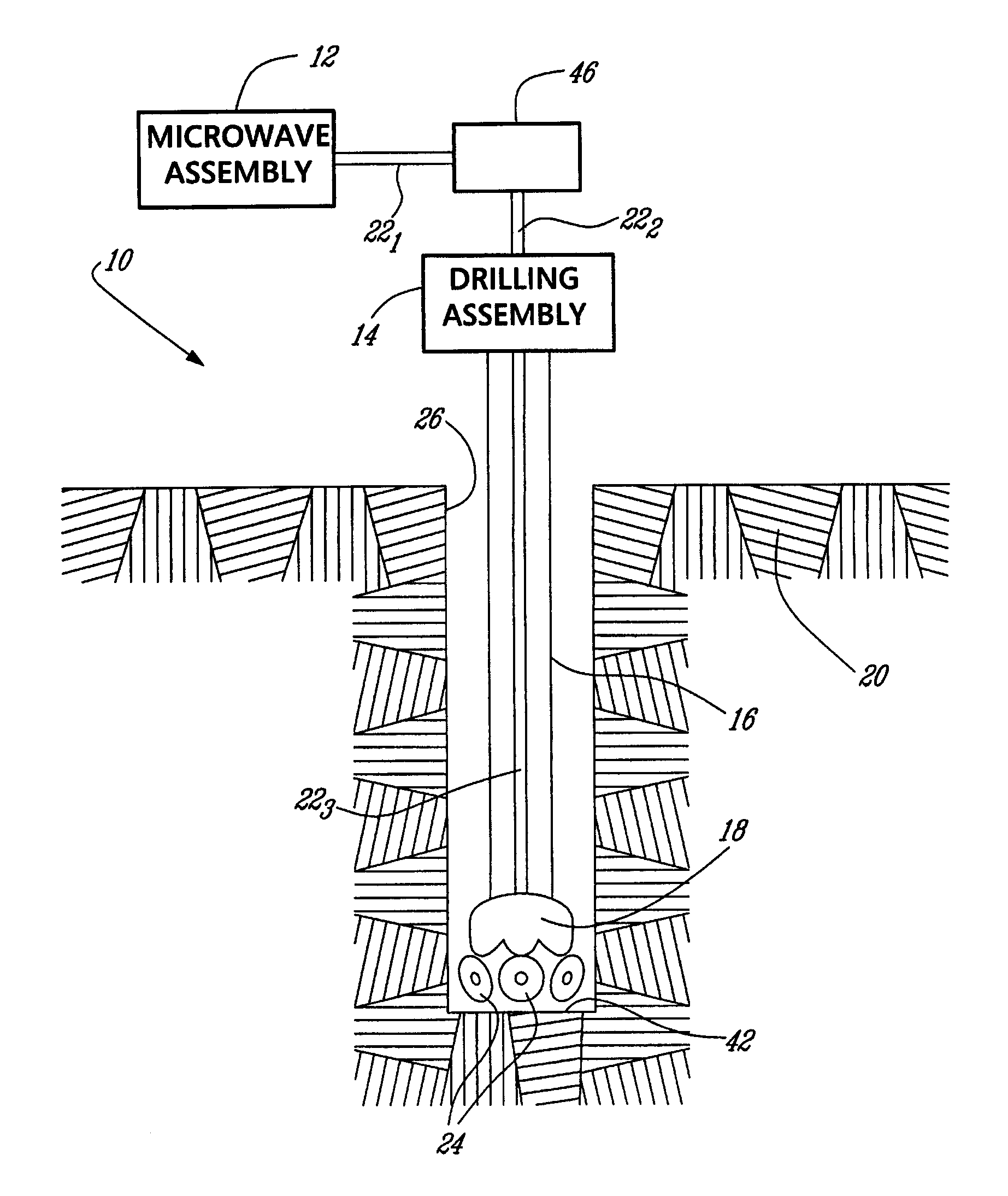
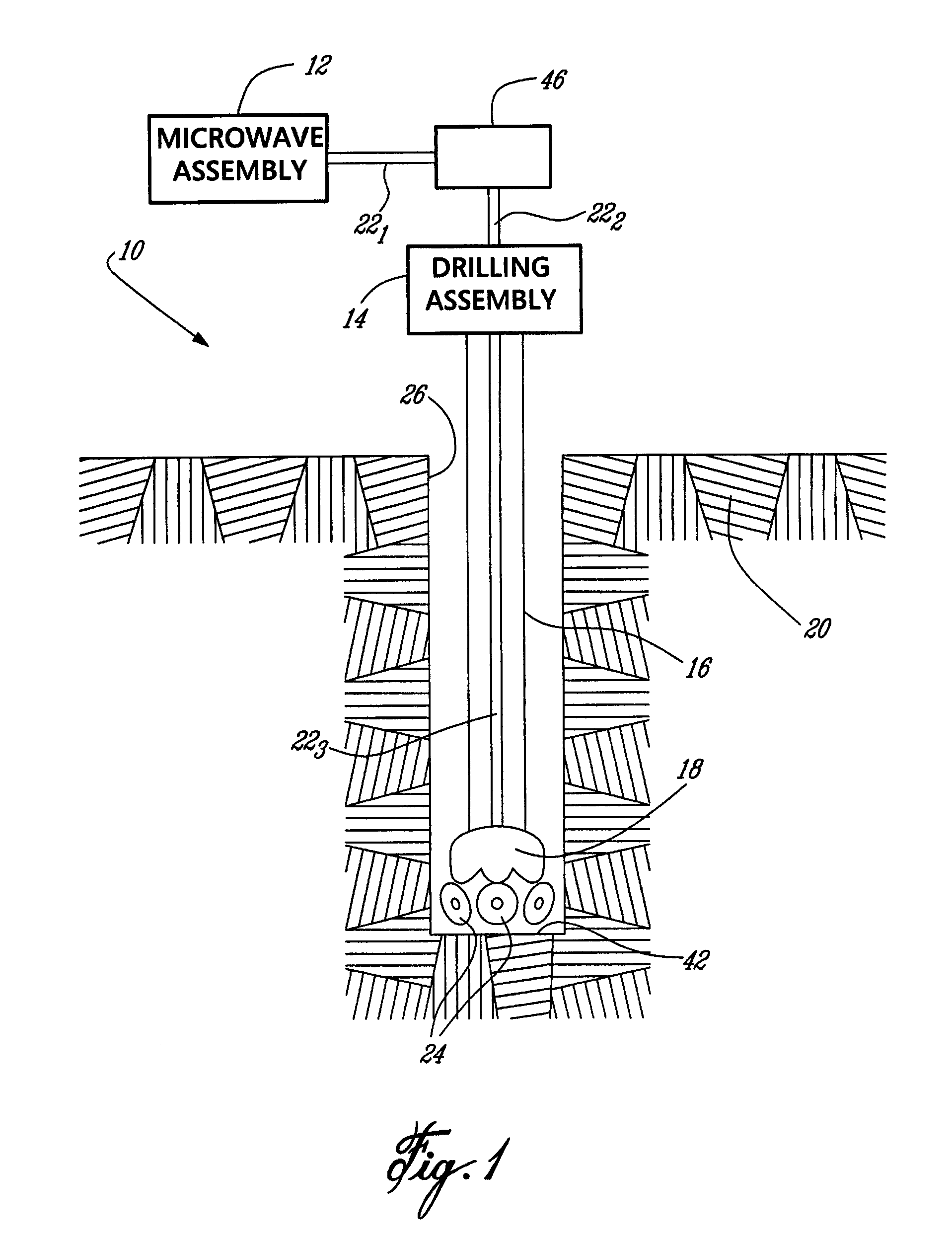
[0018]Referring to FIG. 1, an electromagnetic energy assisted mining system, generally referred to using the reference numeral 10, will now be described. The system 10 is illustratively comprised of a microwave assembly 12 for generating microwave energy and a drilling assembly 14 comprising a drill rod (or string) 16 and an excavation bit 18 for drilling into an aggregate 20. The microwave assembly 12 and the drilling assembly 14 are interconnected by a transmission line comprised of a series of waveguides as in 22 and interconnected in order to transfer the microwave energy generated by the microwave assembly 12 to a point proximate the excavation bit 18. In operation, and as will be apparent to a person of ordinary skill in the art, the excavation bit 18, by means of one or more cutting heads 24, excavates or otherwise bores (typically by rotary motion or impact force) a shaft 26 in the aggregate 20.

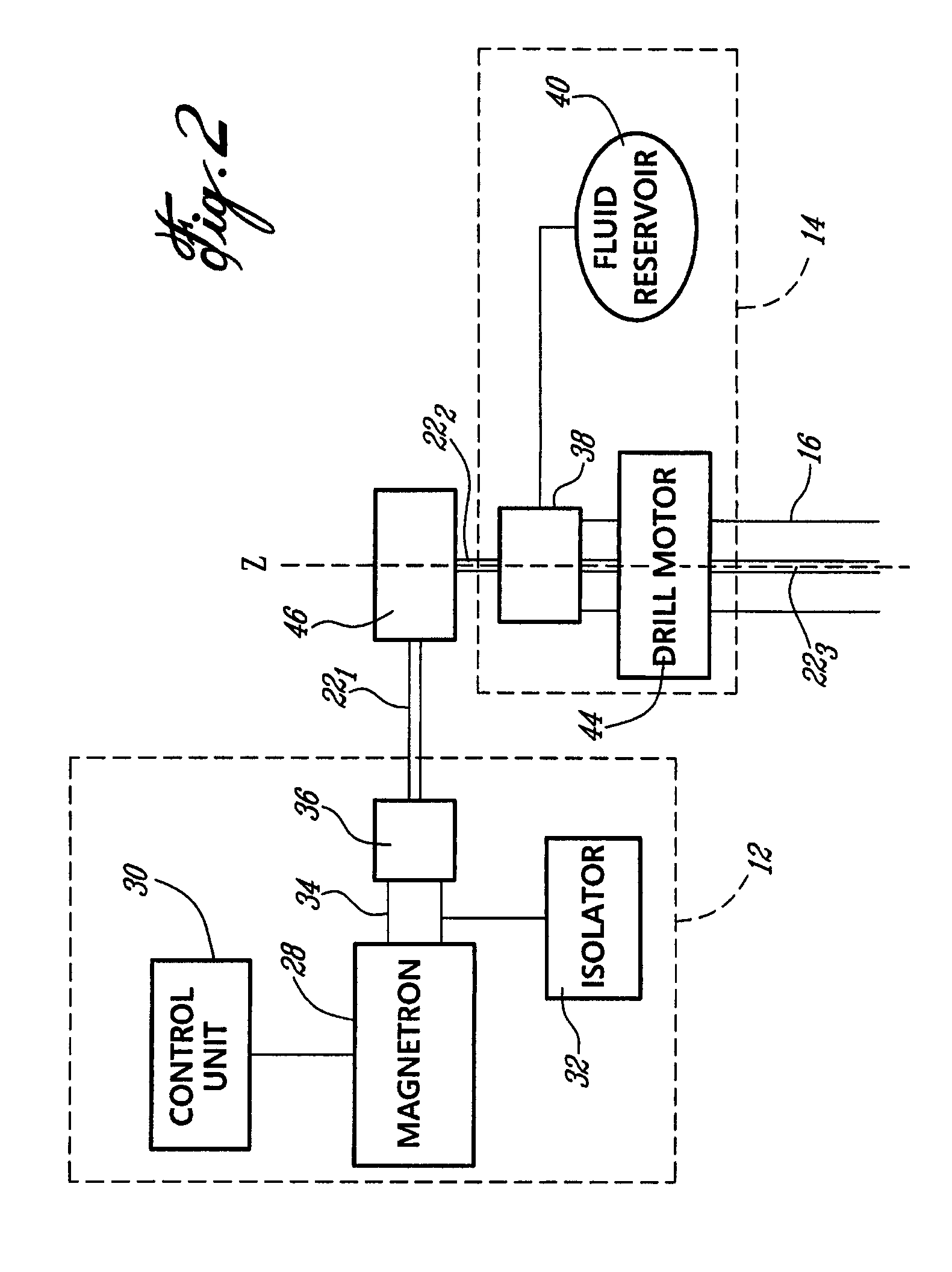
[0019]Referring now to FIG. 2 in addition to FIG. 1, the microwave assembly 12 is...


PUM


Abstract

A drill bit, system and method for penetrating a material such as a mineral bearing rock or the like. The system comprises a drill bit comprising a cutting face comprising at least one cutting tool, an emitter of microwaves positioned behind the cutting face, wherein at least a portion of the microwaves are emitted in a direction away from the cutting face, and a reflector for directing the portion to the cutting face. In operation the emitted microwaves irradiate the material prior to the irradiated material being removed by the at least one cutting tool.

Description

CROSS-REFERENCE TO RELATED APPLICATIONS[0001]This application is a National Entry Application of PCT application no PCT / CA2007 / 001343 filed on Jul. 30, 2007 and published in English under PCT Article 21(2), which itself claims priority on U.S. provisional application Ser. No. 60 / 820,687, filed on Jul. 28, 2006. All documents above are incorporated herein in their entirety by reference.TECHNICAL FIELD[0002]The present invention relates to an electromagnetic energy assisted drilling system and method. More specifically, the present invention relates to a system and method wherein a material such as rock, which prior to excavation using a cutting tool such as a drill is first exposed to low energy microwave radiation in order to reduce the strength of the rock and improve drilling efficiency.BACKGROUND OF THE INVENTION[0003]A variety of mechanical machines, such as drilling, tunnelling and continuous mining machines are available for cutting rock formations. One drawback of these prior...

Claims


Application Information

Patent Timeline
Patent Type & Authority Patents(United States)
IPC IPC(8): E21B7/14E21B10/00
CPCE21B7/15E21C37/18H05B6/80
Inventor OUELLET, JACQUESRADZISZEWSKI, PETERRAGHAVAN, VIJAYASATISH, HEMANTHHASSANI, FERRI
Owner MCGILL UNIV
Learn More