Imaging area specifying apparatus, radiographic system, imaging area specifying method, radiographic apparatus, and imaging table

a radiographic system and imaging area technology, applied in the direction of instruments, diaphragms for radiation diagnostics, patient positioning for diagnostics, etc., can solve the problems of specific portion deterioration, and more expensive electronic cassettes than cassettes including x-ray films. to achieve the effect of preventing the deterioration of specific portion

Inactive Publication Date: 2013-10-08
FUJIFILM CORP
View PDF10 Cites 29 Cited by
  • Summary
  • Abstract
  • Description
  • Claims
  • Application Information

AI Technical Summary

Benefits of technology

[0020]The invention has been made in order to solve the above-mentioned problems, and an object of the invention is to provide an imaging area specifying apparatus, a radiographic system, and a method of specifying an imaging area capable of preventing the deterioration of a specific portion of a detection region of a radiation detector.
[0021]Another object of the invention is to provide a radiographic apparatus and an imaging table capable of preventing the deterioration of a specific portion of a detection region of a radiation detector.

Problems solved by technology

Meanwhile, the electronic cassette is more expensive than the cassette including the X-ray film or the imaging plate.
However, in the technique disclosed in JP-A No. 2003-33343, in some cases, a specific portion of the detection region of the radiation detector deteriorates.
Therefore, in a case in which an imaging operation is repeatedly performed using a specific portion of the detection region of the radiation detector, only that portion deteriorates.
However, when an imaging operation is repeatedly performed using a central portion of the detection region, the central portion deteriorates, and the quality of the radiological image captured in the central portion deteriorates.
In addition, in a case in which an imaging operation is performed using the entire detection region of the radiation detector, there is a difference in quality between the images captured in the central portion and a peripheral portion.
For example, in fluorography, in general, the imaging area is limited to the central portion of the radiation detector and the central portion deteriorates.
However, Japanese Patent No. 2716949 and JP-A-2009-17484 do not disclose any measures to prevent the deterioration.
However, a region to which radiation is emitted in the radiation detector deteriorates.
However, it is difficult to perform the removal process while a moving image is captured.
However, in the techniques disclosed in JP-A No. 2000-134539 and JP-A No. 2007-215760, in some cases, a specific portion of the detection region of the radiation detector deteriorates.
For example, when an imaging operation is repeatedly performed using a central portion of the detection region, the central portion deteriorates, and the quality of the radiological image captured in the central portion deteriorates.

Method used


Image

  • Imaging area specifying apparatus, radiographic system, imaging area specifying method, radiographic apparatus, and imaging table
  • Imaging area specifying apparatus, radiographic system, imaging area specifying method, radiographic apparatus, and imaging table
  • Imaging area specifying apparatus, radiographic system, imaging area specifying method, radiographic apparatus, and imaging table

Examples


first embodiment

[0091][First Embodiment]

[0092]First, the structure of a radiology information system 10 according to this embodiment will be described.

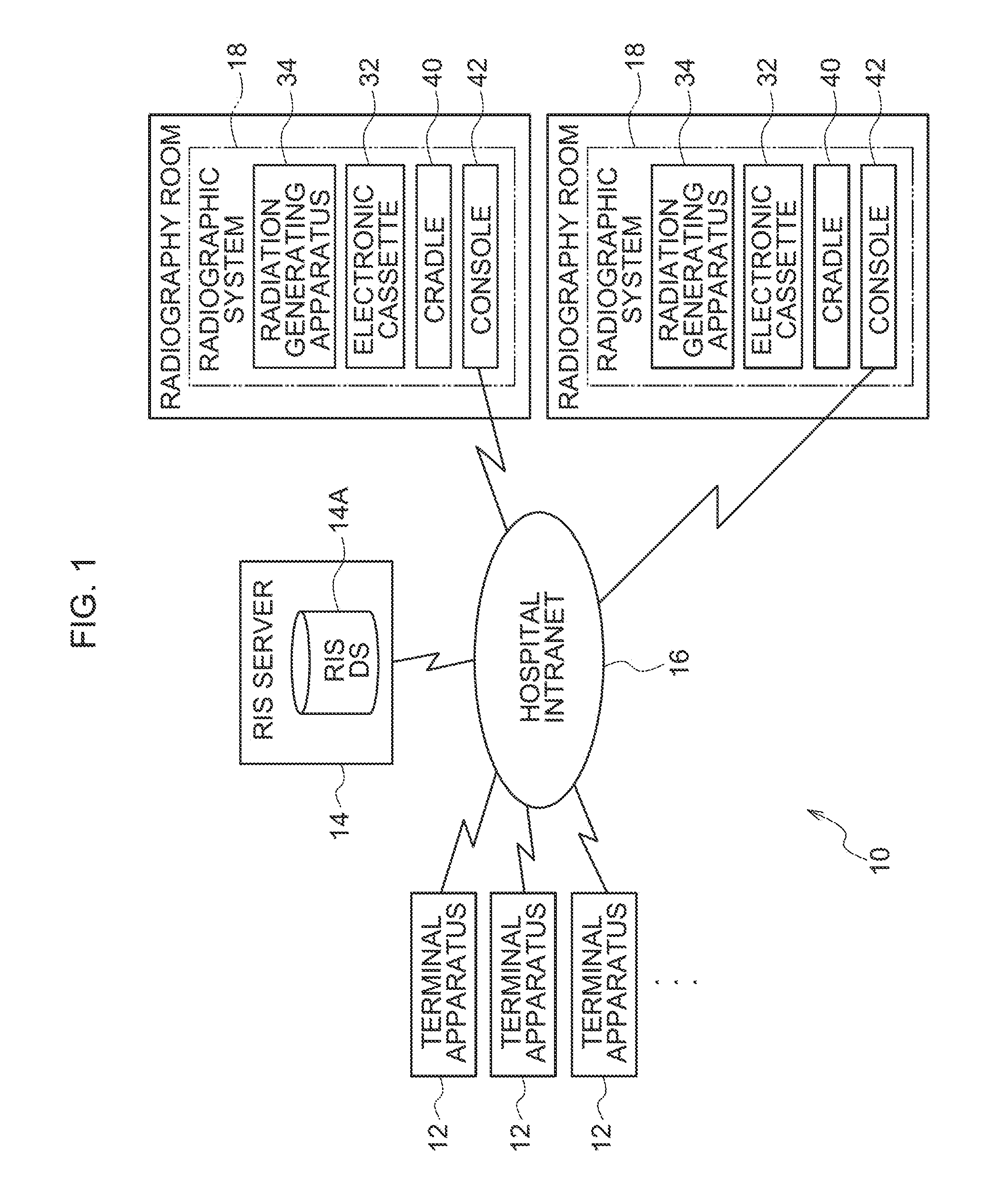
[0093]FIG. 1 is a block diagram illustrating each component of the radiology information system 10 (hereinafter, referred to an “RIS 10”) according to this embodiment.

[0094]The RIS 10 is a system for managing information, such as a medical reservation and a diagnosis record, in the department of radiology and forms a portion of a hospital information system (hereinafter, referred to as an “HIS”).

[0095]The RIS 10 includes plural imaging request terminal apparatuses 12 (hereinafter, also referred to as “terminal apparatuses 12”), an RIS server 14, and plural radiographic systems 18 (hereinafter, also referred to as “imaging systems 18”) that are provided in each radiography room (or an operating room) in the hospital, and the components are connected to a hospital intranet (a network in a hospital) 16, such as a wired or wireless LAN (Local Area Networ...

second embodiment

[0216][Second Embodiment]

[0217]Next, a second embodiment will be described.

[0218]The structure of a radiology information system 10 according to the second embodiment is the same as that according to the first embodiment (see FIGS. 1 and 2) and thus a description thereof will be omitted.

[0219]FIG. 14 shows the structure of an electronic cassette 32 according to the second embodiment. The same components as those in the first embodiment (see FIG. 7) are denoted by the same reference numerals and a description thereof will be omitted.

[0220]The electronic cassette 32 according to the second embodiment includes a touch panel 57 that is provided integrally with an irradiation surface 56. The touch panel 57 may be any of a pressure-sensitive type, a resistance film type, a capacitance type, an optical scanning type, and an ultrasonic type. In this embodiment, one touch panel 57 is provided for the irradiation surface 56. However, the touch panel 57 may be provided for each area 56A.

[0221]...

third embodiment

[0268][Third Embodiment]

[0269]First, the structure of a radiology information system 10 according to this embodiment will be described.

[0270]FIG. 1 is a block diagram illustrating each component of the radiology information system 10 (hereinafter, referred to an “RIS 10”) according to this embodiment.

[0271]The RIS 10 is a system for managing information, such as a medical reservation and a diagnosis record, in the department of radiology and forms a portion of a hospital information system (hereinafter, referred to as an “HIS”).

[0272]The RIS 10 includes plural imaging request terminal apparatuses 12 (hereinafter, also referred to as “terminal apparatuses 12”), an RIS server 14, and plural radiographic systems 18 (hereinafter, also referred to as“imaging systems 18”) that are provided in each radiography room (or an operating room) in the hospital, and the components are connected to a hospital intranet 16, such as a wired or wireless LAN (Local Area Network). An HIS server that mana...


PUM


Abstract

An imaging area specifying apparatus that includes a storage component and a specifying component is provided. The storage component stores as correlation information a correlation value correlated with the amount of radiation emitted to each of a plurality of predetermined areas divided from a detection region of a radiation detector that outputs an electric signal indicating a radiological image represented by radiation which is emitted to the detection region for detecting the radiation. The specifying component specifies an imaging area capable of capturing the radiological image of a predetermined size while preventing variations in the amount of radiation emitted to each of the divided areas in the detection region, on the basis of the correlation information stored in the storage component.

Description

CROSS-REFERENCE TO RELATED APPLICATION[0001]This application is based on and claims priority under 35 USC 119 from Japanese Patent Applications No. 2009-256473 filed on Nov. 9, 2009, No. 2010-000679 filed on Jan. 5, 2010, No. 2010-236810 filed on Oct. 21, 2010 and No. 2010-236811 filed on Oct. 21, 2010, the disclosures of which are incorporated by reference herein.BACKGROUND OF THE INVENTION[0002]1. Field of the Invention[0003]The present invention relates to an imaging area specifying apparatus, a radiographic system, an imaging area specifying method, a radiographic apparatus, and an imaging table.[0004]2. Description of the Related Art[0005]In recent years, radiation detectors, such as flat panel detectors (FPD) that include a radiation sensitive layer provided on a thin film transistor (TFT) active matrix substrate, detect radiation, such as X-rays emitted, and output an electric signal indicating a radiological image represented by the detected radiation, have been put to pract...

Claims


Application Information

Patent Timeline
Patent Type & Authority Patents(United States)
IPC IPC(8): G01D18/00G21K1/00
CPCA61B6/04A61B6/06A61B6/4283A61B6/5241A61B6/542A61B6/4476A61B6/4291
Inventor NISHINO, NAOYUKITAKAHASHI, KENJINAKATSUGAWA, HARUYASUYOSHIDA, YUTAKATSUBOTA, KEIJIOHTA, YASUNORI
Owner FUJIFILM CORP
Why Eureka
Try Eureka