
Automated system for anatomical vessel characteristic determination

a technology of anatomical blood vessels and display systems, applied in the field of anatomical blood vessel detection and display systems, can solve the problems of time-consuming and easy to error detection, system for blood vessel detection, and erroneous detection of vessel boundaries, and achieve the effect of inhibiting erroneous detection of boundaries

Active Publication Date: 2013-10-08
SIEMENS HEALTHCARE GMBH
View PDF20 Cites 9 Cited by
  • Summary
  • Abstract
  • Description
  • Claims
  • Application Information

AI Technical Summary

Benefits of technology

The patent describes a system that allows a user to mark a specific part of a vessel in an image and have the system automatically detect the boundaries of that vessel. This ensures that the system does not mistakenly detect borders in other parts of the image. The system then displays the detected vessel and its boundaries on a screen. This system can help healthcare professionals easily identify and locate blood vessels in images, which can be useful in medical diagnosis and treatment.

Problems solved by technology

In known blood vessel detection applications, blood vessel detection involves multiple user interactions making detection both time consuming and prone to error.
Known systems for blood vessel detection experience problems including, erroneous detection of vessel boundaries, excessive use of computation resources, inflexibility.
Known systems also often require burdensome iterative trial and error processing.
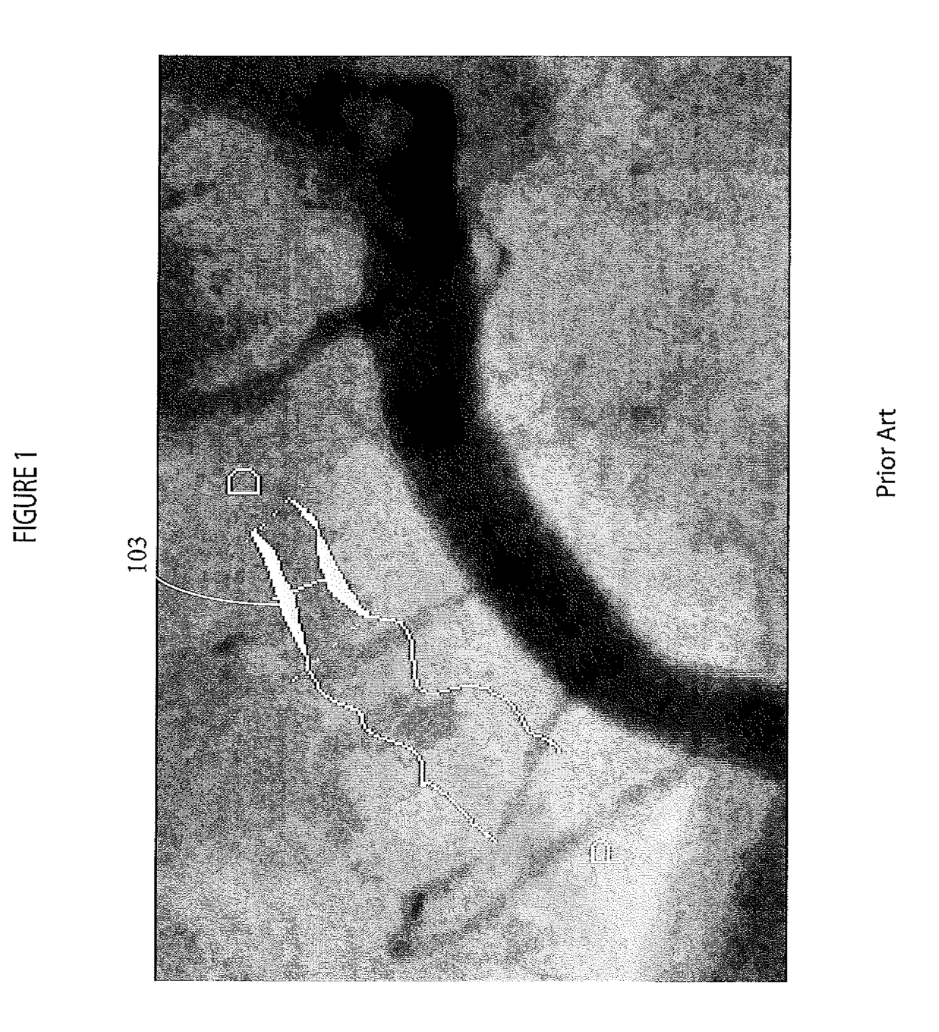
A user of a known system may inadvertently select a region outside of a vessel area resulting in erroneous detection of a non-existent vessel boundary as illustrated in FIG. 1 in the erroneously detected boundary 103 in a region of interest outside of a real vessel boundary.
Known systems also lack flexibility in enabling a user to extend an already detected portion of a vessel boundary to a different vessel portion and may require complete image vessel re-detection.
Known methods typically do not allow extension of a detected vessel to an undetected portion.
Known methods also do not allow a user to extend vessel boundary detection to a side branch of an already detected main vessel branch through a bifurcation, for example.
Known vessel detection methods involve repetitive trial and error steps when smaller diameter vessels have to be detected and a detected vessel boundary may not fit an actual boundary.
This results in a user having to correct a detected boundary or delete the boundary in order to manually mark the vessel in the region of interest and initiate vessel detection to match the actual boundary.
Further, known methods involve burdensome computation and perform vessel detection each time a user selects a region in the same image.
This leads to unnecessary repetitive computation to detect a vessel boundary in the selected region of interest.

Method used


Image

  • Automated system for anatomical vessel characteristic determination
  • Automated system for anatomical vessel characteristic determination
  • Automated system for anatomical vessel characteristic determination

Examples


Embodiment Construction

[0024]A system enables a user to mark a ROI of a vessel portion having detected boundaries and extend the automatic detection of vessel boundaries into a region identified by the user. The system automatically determines a minimum vessel diameter in the extended marked region of interest between the detected boundaries and initiates identification of the location of the minimum vessel diameter in the image.

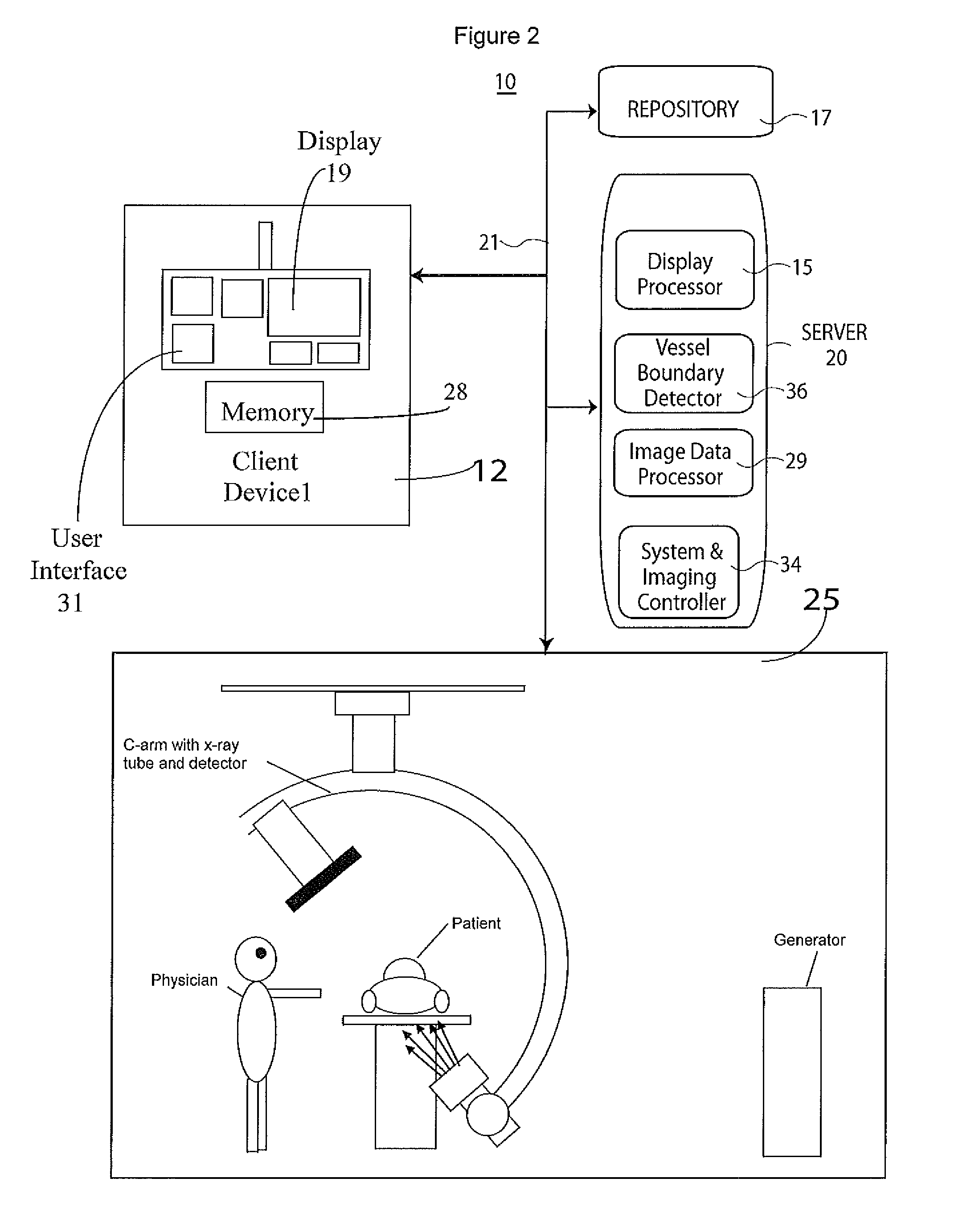
[0025]FIG. 2 shows anatomical blood vessel detection and display system 10. System 10 includes one or more processing devices (e.g., workstations or portable devices such as notebooks, computers, Personal Digital Assistants, phones) 12 that individually include a user interface control device 31 such as a keyboard, mouse, touchscreen, voice data entry and interpretation device and memory 28. System 10 also includes at least one repository 17, X-ray imaging modality system 25 (which in an alternative embodiment may comprise an MR (magnetic resonance), CT scan, or Ultra-sound system...


PUM


Abstract

A system enables a user to mark a ROI of a vessel portion having detected boundaries and extend the detection of vessel boundaries into a region identified by the user. An anatomical blood vessel detection and display system includes a user interface enabling a user, via a display of an image presenting anatomical vessels, to, mark a region of interest in a vessel identified by detected boundaries in the image and extend the marked region of interest of the vessel. A detector automatically detects a boundary of the vessel in the extended marked region of interest by detecting an edge representing a change in luminance in data representing the image. An image data processor identifies a minimum vessel diameter in the extended marked region of interest between the detected boundaries and initiates identification of the location of the minimum vessel diameter in the image.

Description

FIELD OF THE INVENTION[0001]This invention concerns an anatomical blood vessel detection and display system enabling a user, via a display of an image presenting anatomical vessels, to extend a marked region of interest of a vessel and automatically detect a boundary of the vessel in the extended marked region of interest.BACKGROUND OF THE INVENTION[0002]In known blood vessel detection applications, blood vessel detection involves multiple user interactions making detection both time consuming and prone to error. Known systems for blood vessel detection experience problems including, erroneous detection of vessel boundaries, excessive use of computation resources, inflexibility. Known systems also often require burdensome iterative trial and error processing. A user of a known system may inadvertently select a region outside of a vessel area resulting in erroneous detection of a non-existent vessel boundary as illustrated in FIG. 1 in the erroneously detected boundary 103 in a regio...

Claims


Application Information

Patent Timeline
Patent Type & Authority Patents(United States)
IPC IPC(8): G06K9/00G06K9/48G06T17/00A61B5/02G06K9/40G06K9/36G06K9/20
CPCG06T7/0085G06T7/602G06T2207/10116G06T2207/20104G06T2207/30101G06T7/13G06T7/62
Inventor SAIKIA, HRISHIKESH
Owner SIEMENS HEALTHCARE GMBH
Learn More