Feed beater directional vanes and scraper vanes

a directional vanes and directional vanes technology, applied in the field of combine harvesters, can solve the problems of increased back-feeding of the crop stream, significant factor on the power consumption of the machine, and notably apparen

Active Publication Date: 2013-10-15
AGCO AS
View PDF25 Cites 12 Cited by
  • Summary
  • Abstract
  • Description
  • Claims
  • Application Information

AI Technical Summary

Benefits of technology

[0007]It is therefore an object of the present invention to provide an improved harvester of the kind d

Problems solved by technology

It is well recognised that the mechanism by which the crop flow is conveyed from the transverse threshing drum to the twin rotor housings is a significant factor on the power consumption of the machine.
However, it has been found that the directional vanes of the feed beater lead to increased back-feeding of the crop stream around a central part of the feed beater.
This problem is particul

Method used


Image

  • Feed beater directional vanes and scraper vanes
  • Feed beater directional vanes and scraper vanes
  • Feed beater directional vanes and scraper vanes

Examples


Embodiment Construction

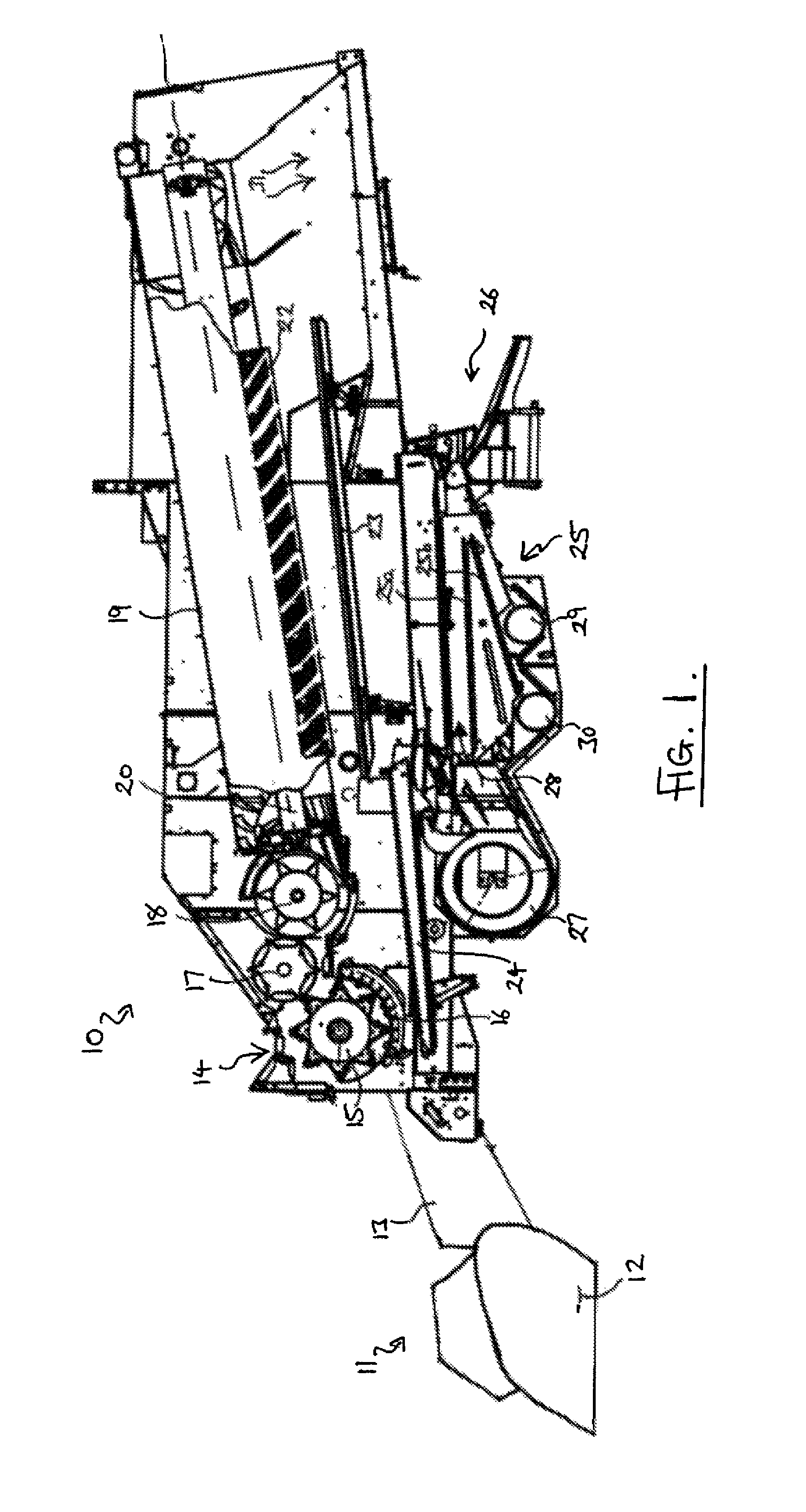
[0025]With reference to FIG. 1, a combine harvester 10 comprises a header 11 detachably mounted at the front end thereof. The header 11 includes a cutter mechanism 12 and a feed mechanism having an enclosed elevator 13 which feeds harvested crop material into a transverse threshing drum 14. The threshing drum 14 comprises a rotating threshing cylinder 15 and a concave 16. Within the drum 14 the crop material is threshed by the cylinder 15 and a proportion of the separated grain falls through a grill in the concave 16. The remaining crop material is conveyed in a stream by the rotating motion of the cylinder 15, exiting the rear of the drum 14, and transferred rearwardly by a transfer beater 17 to a feed beater 18.

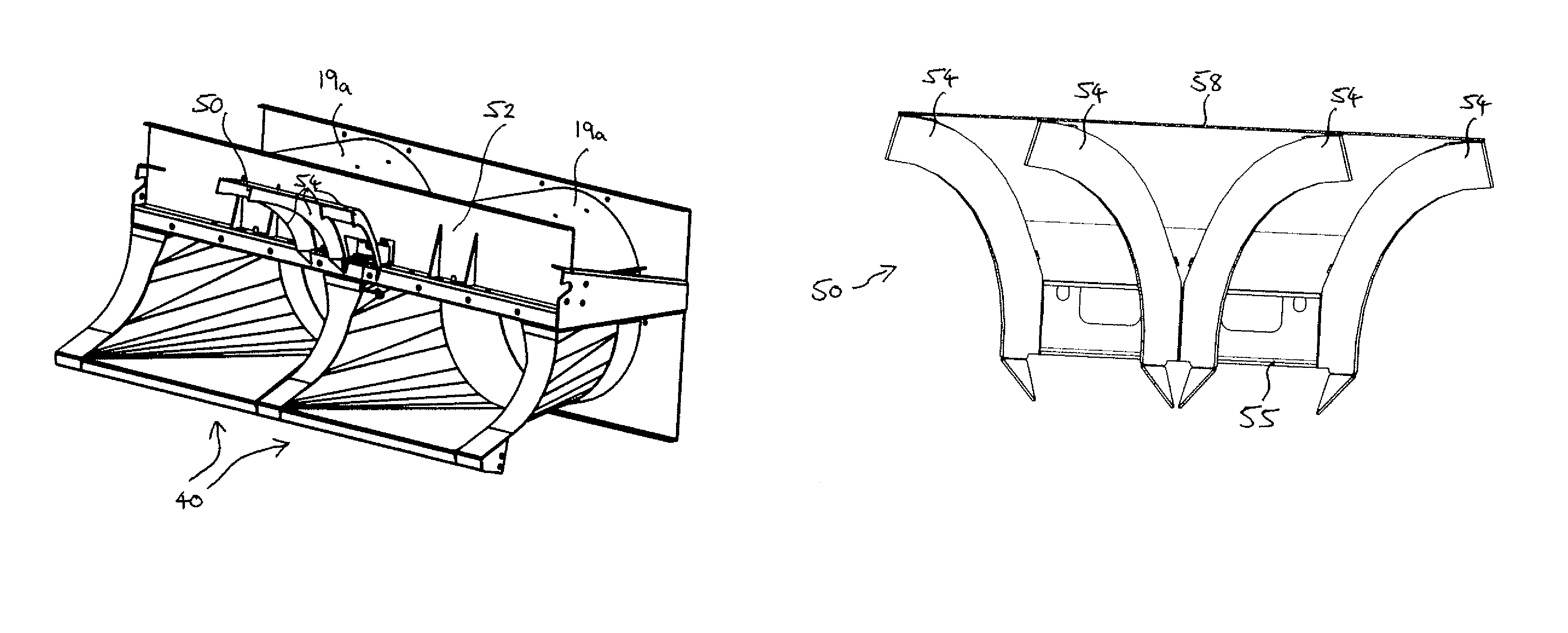
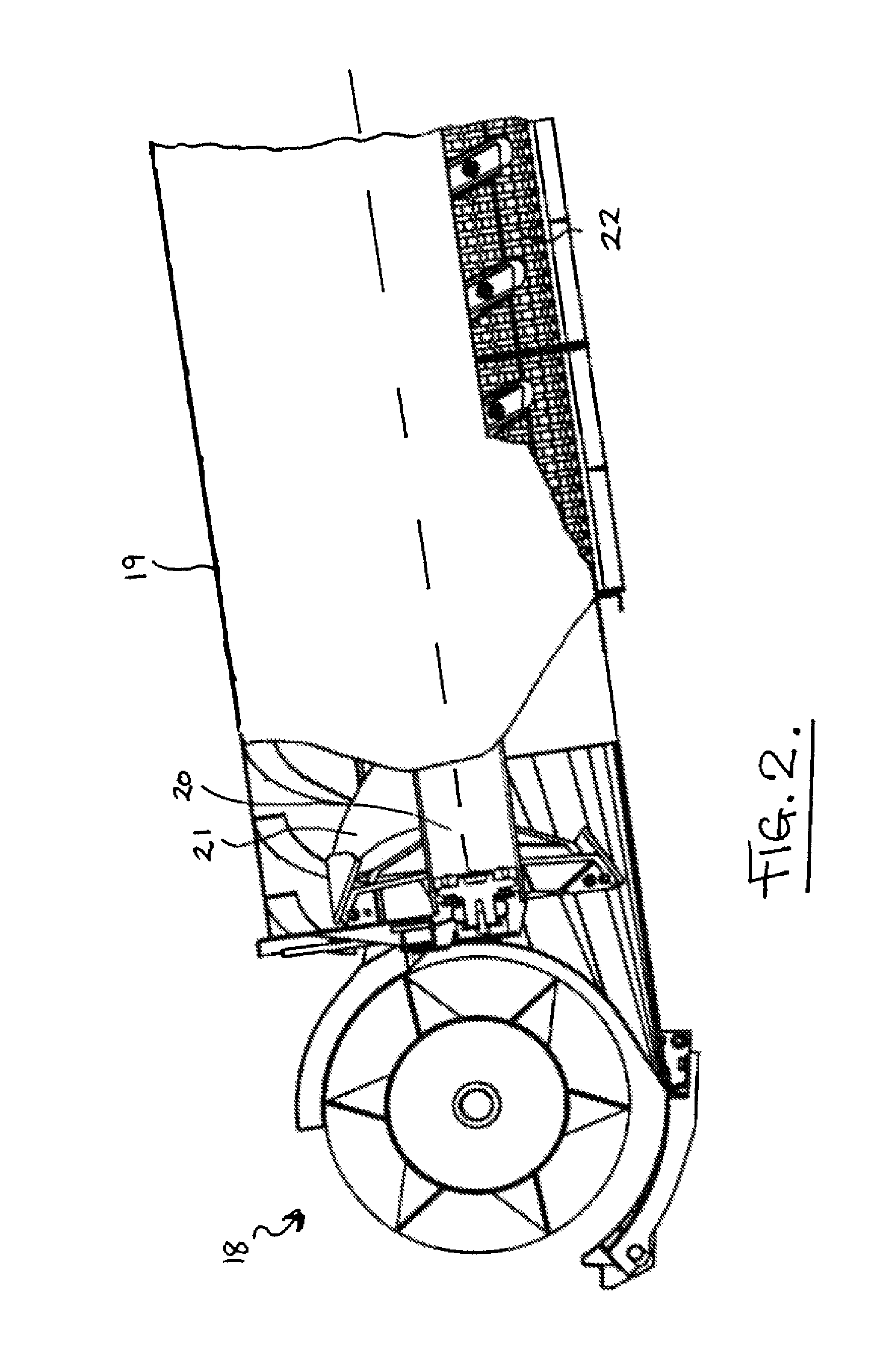
[0026]The crop material passes under the feed beater 18 and is transferred into respective housings 19 of axial separating rotors 20, each extending side-by-side in a longitudinal direction. Once divided, the separate crop streams are conveyed rearwardly, and in a corkscrew...


PUM


Abstract

A combine harvester (10) comprising a pair of axial separating rotors (20) each extending side-by-side within respective housings (19) in a longitudinal direction and serving to separate grain from straw. A feed beater (18) is provided which rotates on a transverse axis (X) and is located in front of the separating rotors to direct a crop flow rearwardly under the feed beater. Directional vanes (34) on the feed beater direct the crop flow away from a central zone of the beater and toward respective crop streams associated with the two rotors. Scraper apparatus (50) comprising stationary vanes (54) are provided above the beater. Crop material which back feeds over the top of the beater is scraped free of the beater and directed outwardly by the stationary vanes so that the scraped material is re-fed under the beater away from the central zone.

Description

BACKGROUND OF THE INVENTION[0001]This invention relates to combine harvesters and in particular to such harvesters (hereinafter referred to as being of the kind described) which have twin axial separating rotors and a transverse feed beater under which a crop stream is conveyed before entering rotor housings for processing by the rotors, flights being provided on the feed beater which tend to move the crop passing under the beater axially outwardly from a central zone of the beater into the two rotors.[0002]There are two main types of separating apparatus used within combine harvesters to separate grain from the straw with which it grows. In traditional combines used mainly in Europe, the threshed crop material is separated by means of a plurality of longitudinally-extending straw walkers which oscillate so as to ‘walk’ the straw to the rear of the combine whilst allowing the grain to drop through sieves formed in the base thereof. This technology is well established and has been ac...

Claims


Application Information

Patent Timeline
IPC IPC(8): A01F12/10
CPCA01F7/067A01F12/10A01F12/442
Inventor BOJSEN, THOMASSORENSEN, JAKOBBALTSER, MIKKELRASMUSSEN, BJARNESORENSEN, HENNING
Owner AGCO AS
Why Eureka
Try Eureka