Digital pulse reject counter

a digital pulse and counter technology, applied in pulse manipulation, pulse technique, instruments, etc., can solve the problems of motor monitoring systems deprived of useful information, the number of pulses rejected by the detection system is not accounted for, and the electrical signals produced by motor-coupled sensors are typically susceptible to nois

Active Publication Date: 2013-10-15
ROCKWELL AUTOMATION TECH
View PDF6 Cites 0 Cited by
  • Summary
  • Abstract
  • Description
  • Claims
  • Application Information

AI Technical Summary

Benefits of technology

[0005]The present invention provides a system and a method designed to respond to such needs. The present technique is based upon the use of a digital pulse rejection counter that is configured to classify and quantify rejected noise pulses generated by sensors coupled to a load, such as a motor. Accordingly, the system and method enable counting rejected pulses by employing predetermined thresholds configured to classify such pulses according to their time durations. In this manner, it is possible to distinguish between different types of noise signals indicative of various processes occurring in the load or in the vicinity thereof. Such a system and method can help assess the performance of the motor, as well as diagnose and preempt present and future malfunctions associated with motor operability. The information is also highly useful in evaluating factors leading to noise, such as installation of wiring, degradation of wiring, local disturbance sources, and so forth.

Problems solved by technology

Electrical signals produced by motor-coupled sensors are typically susceptible to noise.
Such noise may originate from the motor itself or from sources exterior to the motor, such as electrical wiring leading to or from the motor, wiring to and from the sensors to the motor, and wiring between the motor to motor monitoring units.
Accordingly, pulses with time durations shorter than the threshold may be rejected by the detection system and, moreover, may not be registered, such that the number of pulses rejected by the detection system is not accounted for.
In most instances, such pulses originate from noise which may go unregistered as motor performance is being monitored.
By not counting the rejected noise signals, motor monitoring systems may be deprived of useful information obtainable from the rejected noise signals to the extent that uncertainties regarding maintenance of the motor and imminent malfunctions thereof may arise.
Similarly, the nature and source of noise-causing disturbances are not appreciated, and in fact, are generally unknown due to the fact that noise itself is simply unappreciated.

Method used


Image

  • Digital pulse reject counter
  • Digital pulse reject counter
  • Digital pulse reject counter

Examples


Embodiment Construction

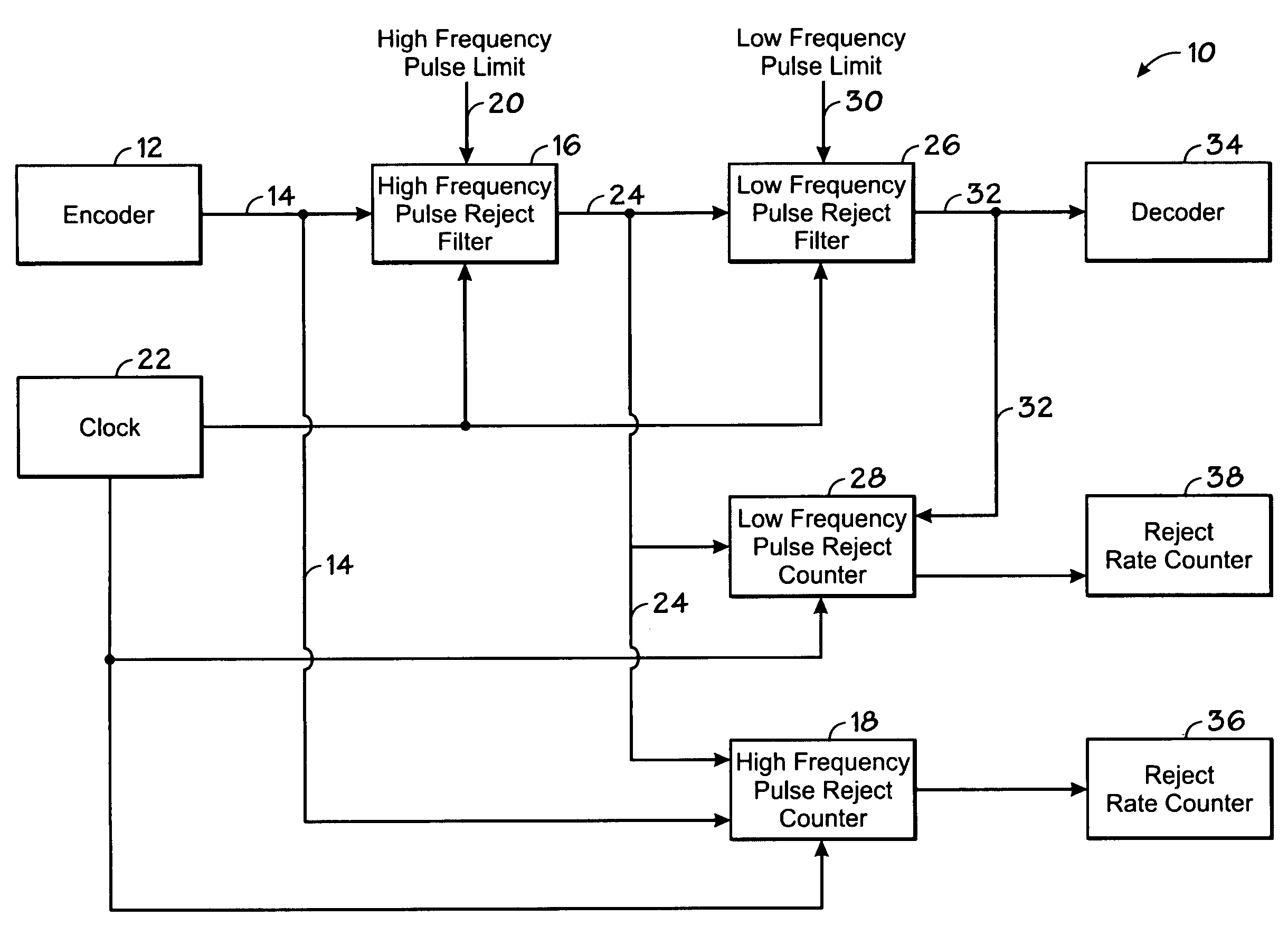
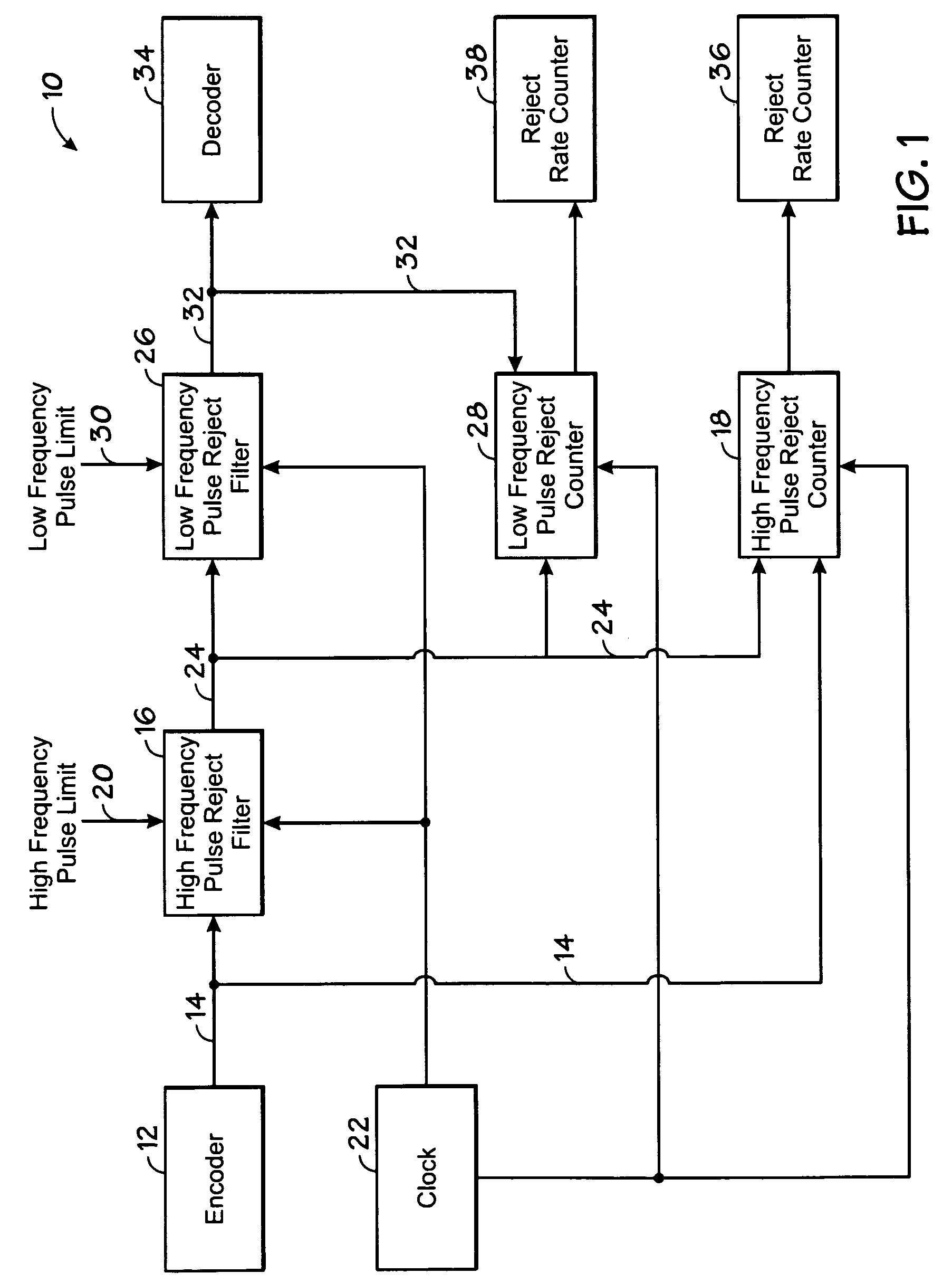
[0010]Turning now to the drawings, and referring first to FIG. 1, a block diagram is shown of an exemplary digital pulse rejection counter system 10, in accordance with an embodiment of the present technique. System 10 may be part of a motor monitoring system configured to monitor signals produced by sensors coupled to the motor. More generally, however, system 10 may be applied to any suitable load. In the illustrated embodiment, system 10 is configured to filter out, (i.e., reject) noise signals above predetermined frequency limits and to count the number of such rejected noise signals. In so doing, system 10 is configured to classify and quantify noise signals according to their frequency ranges (i.e., the duration of time between one signal change [tdl1] and a subsequent signal change).

[0011]System 10 includes an encoder 12 configured to digitally encode signals obtained from a sensor component coupled to a motor. Signals encoded by encoder 12 may comprise, for example, motor sp...


PUM


Abstract

A system and method are provided for filtering noise from a pulsed input signal comprising cyclically producing a change in an output signal only if changes in an input signal occur at least a desired time after a respective immediately previous change in the input signal, and otherwise rejecting the changes in the input signal; and counting the rejected changes in the input signal. More than one duration or frequency may be used for the filtering, enabling classification of noise by frequency. Resulting counts may be used to determine rates of occurrence of noise for evaluation of performance of equipment, installation of the equipment, and changes in performance over time.

Description

BACKGROUND[0001]The present invention relates generally to noise detection in sensed signals. Particularly, this invention relates to a system and method for digitally counting rejected noise signals provided by a motor drive or other sensor.[0002]Motors operated in certain industrial settings are typically monitored for their in-line operational parameters so as to ensure their proper on-going operation, as well as for preempting motor malfunctions. Such in-line parameters may include motor speed, motor shaft angle, motor position and so forth. Detection of such parameters typically requires coupling sensors to the motor for detecting mechanical, thermal or electrical signals produced by or provided to the motor, from which various metrics are obtainable. Such metrics may provide indicators of certain operational states of the motor.[0003]Electrical signals produced by motor-coupled sensors are typically susceptible to noise. Such noise may originate from the motor itself or from s...

Claims


Application Information

Patent Timeline
Patent Type & Authority Patents(United States)
IPC IPC(8): G06F17/10
CPCH03K5/1252H03K5/19
Inventor LUNDELL, THOMAS D.
Owner ROCKWELL AUTOMATION TECH
Why Eureka
Try Eureka