Adaptable bench top filling system

a bench top and filling system technology, applied in the direction of liquid handling, positive displacement liquid engine, packaging goods type, etc., can solve the problems of inconvenient user setup, engender costly downtime, and no user-guided guidance, and achieve maximum flexibility and versatility, and facilitate user setup

Inactive Publication Date: 2013-10-22
EGINTON MICHAEL +1
View PDF28 Cites 13 Cited by
  • Summary
  • Abstract
  • Description
  • Claims
  • Application Information

AI Technical Summary

Benefits of technology

[0016]It is still another object to provide a filling system with software including a graphical user interface displayed on a touch-screen controller for convenient user-setup and establishing and storing various fill recipes and run times.
[0017]These and other objects are accomplished by a semi-automatic bench top filling system that allows the user to switch between different pump technologies while utilizing one base unit. The base unit is outfitted to accommodate peristaltic, lobe, gear, and piston pumps, providing maximum flexibility and versatility in one unit. The base unit employs a computerized servo motor control module and docking hardware for driving any of the four different pump types. The system is designed to automate the filling of sample containers regardless of which pump is mounted by tare weighting, and the drive will adjust itself to dispense the correct weight. The pump drive includes appropriate reduction gearing and quick disconnect flexible couplings for each of the different pump types, a side-mounted universal adapter for connecting a peristaltic, gear, or lobe pump, and a separate piston drive assembly and dock-connector at the rear for a piston pump. The device includes a touch-screen controller with control software for user-setup, establishing different fill recipes and run times.

Problems solved by technology

However, a single peristaltic pump is used so that the system is not suitable for filling applications commanding a gear, lobe, or piston pump such as for example pumping of fluids having included particulate matter.
Acquiring and maintaining multiple pumping systems to be swapped in and out entails a significant investment in equipment and overhead and engenders costly “downtime” when changing from one product (or batch) to another.
However, no user-guidance is given for the changeover, so this process remains burdensome.

Method used


Image

  • Adaptable bench top filling system
  • Adaptable bench top filling system
  • Adaptable bench top filling system

Examples


Embodiment Construction

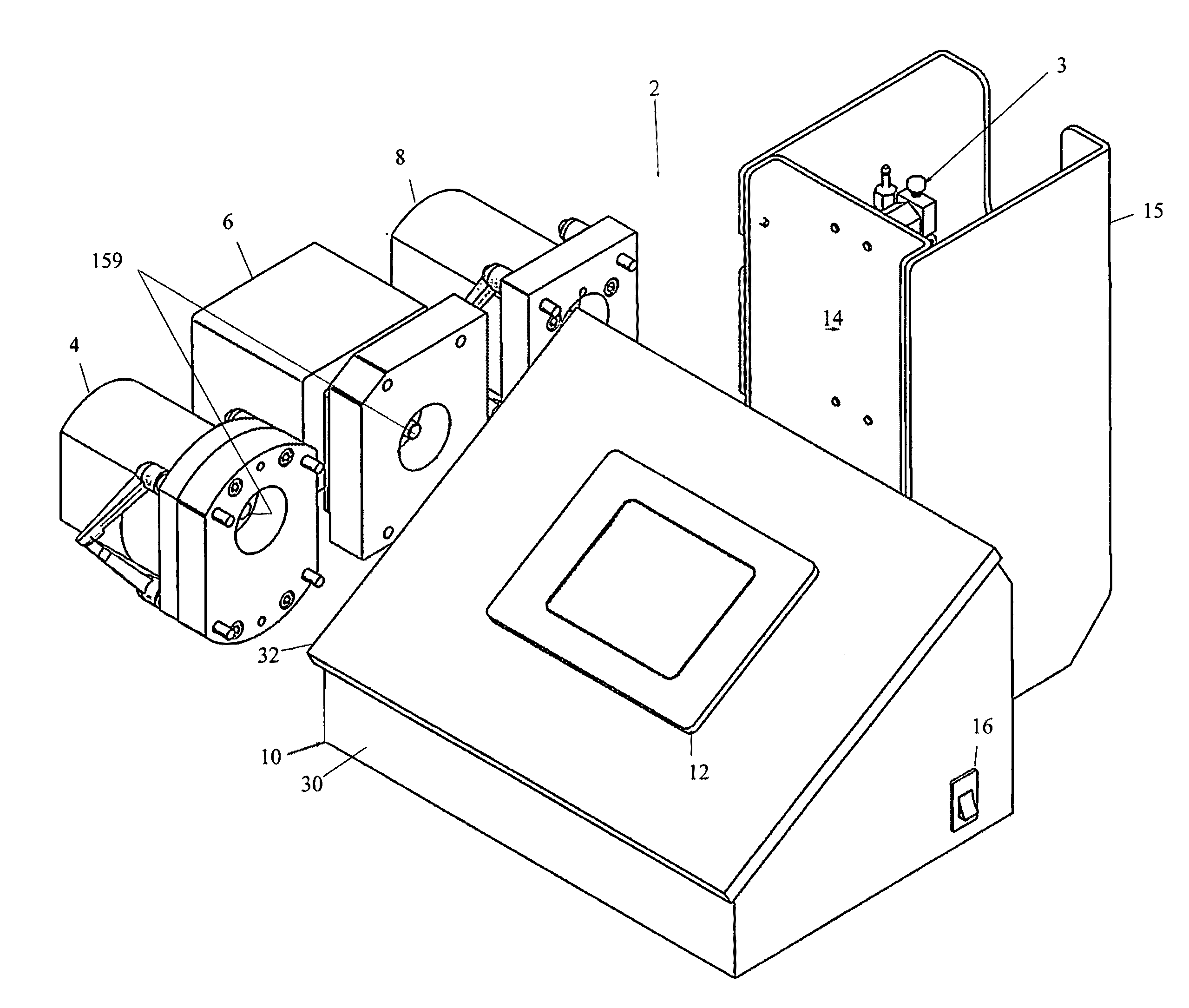
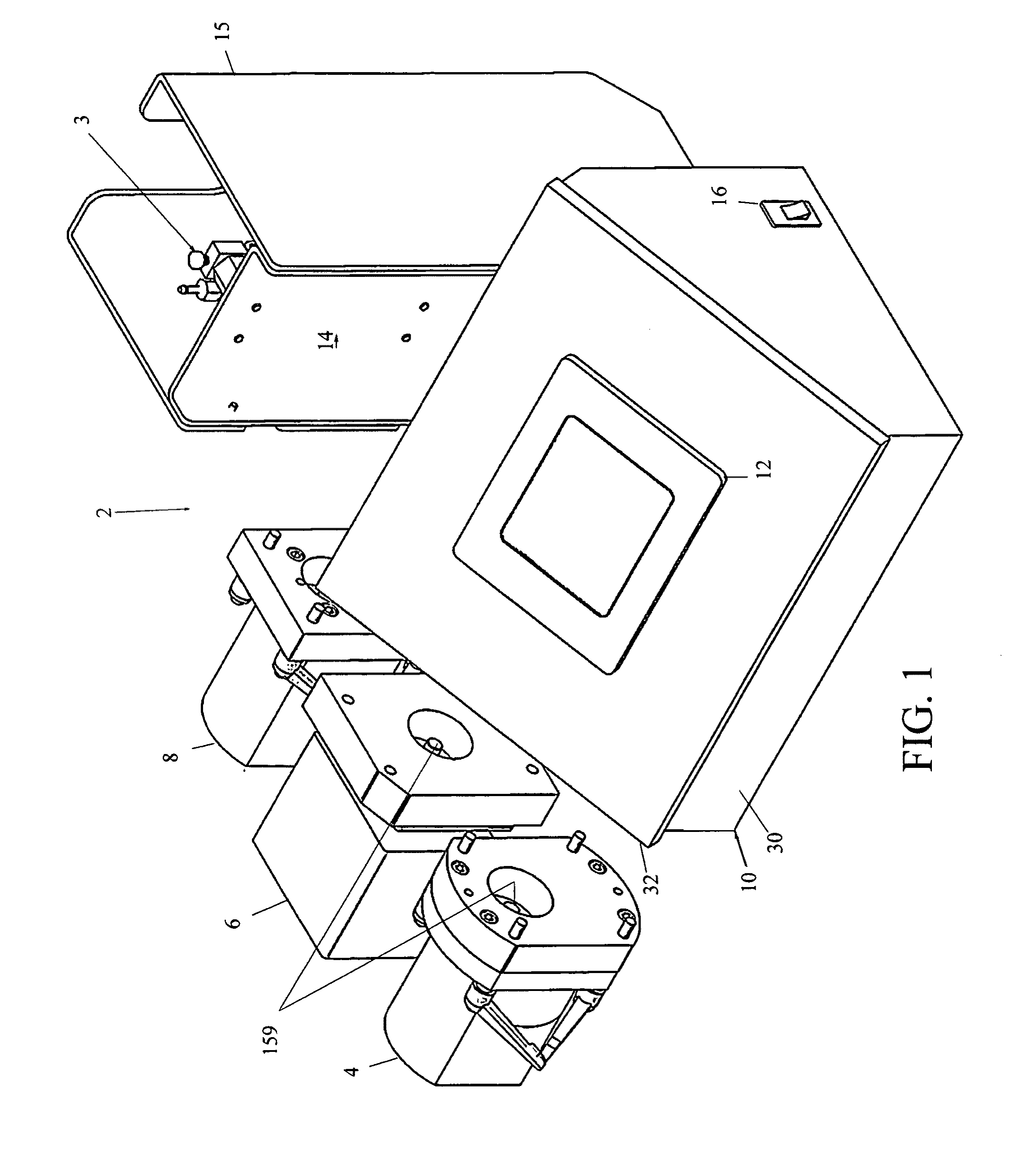
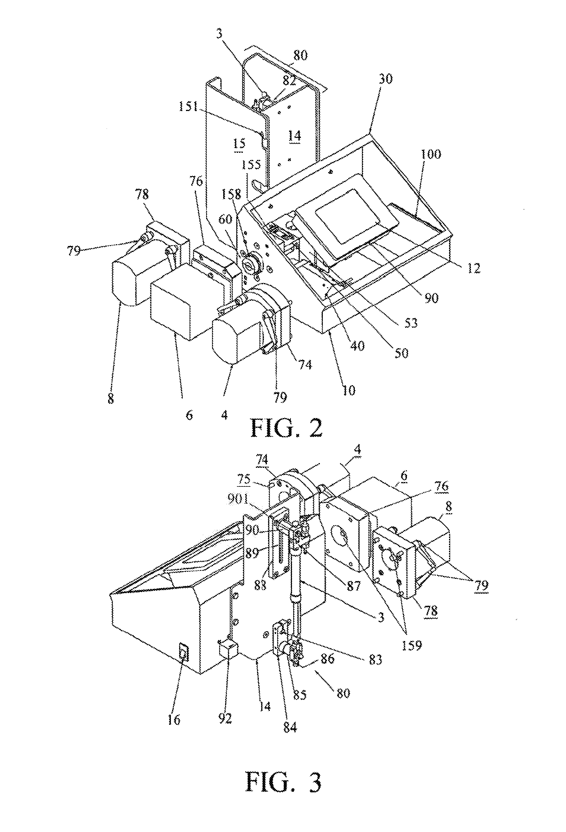
[0028]The present invention is a semi-automatic bench top filling system 2 that allows the user to switch between pump technologies while utilizing a single drive and controller unit. FIG. 1 is a right-side perspective view of a filling system 2 according to a preferred embodiment of the present invention that is equipped to alternately accommodate a peristaltic pump 6, lobe pump 4, gear pump 8, or piston pump 3. The base unit 10 houses an internal servo motor 40 (FIG. 2), a computerized servo motor control module 100 (FIG. 2), and docking mechanism for engaging and driving any of the four different pump types. The peristaltic pump 6, lobe pump 4, gear pump 8 alternately dock at the side of the base unit 10 as described below, while the piston pump 3 is supported on a rear mounting bracket 14 and coupled to a piston pump drive assembly 80 (also described below). The base unit 10 also includes a touch-screen controller interface 12 for user-setup and operation. The base unit 10 inclu...


PUM

PropertyMeasurementUnit
flexibleaaaaaaaaaa
heightaaaaaaaaaa
sizesaaaaaaaaaa

Abstract

A semi-automatic benchtop filling system that allows the user to switch between pump technologies while utilizing one base unit. The base unit is outfitted to accommodate peristaltic, lobe, gear, and piston pumps providing a maximum amount of flexibility and versatility in one unit. The base unit employs a computerized servo motor control system and docking hardware for driving any of the four different pump types. The system is designed to automate the filling of sample containers regardless of which pump is mounted by tare weighting, and the drive will adjust itself to dispense the correct weight. The pump drive includes appropriate reduction gearing and quick disconnect flexible couplings for each of the different pump types, a side-mounted adapter for connecting any of the peristaltic, gear and lobe pumps, and a separate piston drive assembly and dock-connector at the rear for a piston pump. The device includes a touch-screen interface with control software for user-setup, establishing different fill recipes, and run time.

Description

CROSS-REFERENCE TO RELATED APPLICATIONS[0001]The present application derives priority from provisional application 61 / 197,894 filed on Oct. 31, 2008 which is incorporated herein in its entirety by reference.BACKGROUND OF THE INVENTION[0002]1. Field of the Invention[0003]The present invention relates generally to liquid filling systems and, more specifically, to a semi-automated bench top filling system that allows a user to switch between different pump technologies while utilizing a single drive and control unit.[0004]2. Description of the Background[0005]The production container filling industry is faced with a need for filling a wide variety of different types and sizes of containers with different fluids and for running batches as small as only a few units to hundreds or more units. Further, each production run involves specific product requirements that are generally a function of fluid parameters including fill volume (ranging from microliters to liters), viscosity, entrained ...

Claims


Application Information

Patent Timeline
Patent Type & Authority Patents(United States)
IPC IPC(8): B65B3/12
CPCB65B3/12B65B57/145F04B23/10F04B23/12F04B43/12F04B53/22
Inventor EGINTON, MICHAELCHOPPER, JOHN M.
Owner EGINTON MICHAEL
Why Eureka
Try Eureka