LED work light

a technology for led work lights and components, applied in the direction of electric lighting without self-contained power, light fastenings, lighting heating/cooling arrangements, etc., can solve the problems of bulb or filament breakage, bulb breaking with hot filament, fluorescent work lights can experience bulb breakag

Active Publication Date: 2013-10-22
ALLTEMP PROD CO LTD
View PDF101 Cites 18 Cited by
  • Summary
  • Abstract
  • Description
  • Claims
  • Application Information

AI Technical Summary

Problems solved by technology

Incandescent work lights have been in use, but they have some drawbacks.
One drawback is that work lights are all too often dropped or knocked down and fall onto a hard surface, and this often results in breakage of the bulb or its filament.
An additional drawback of incandescent work lights is a safety hazard that results from the possibility of the bulb breaking with its hot filament in close proximity to flammable material such as spilled flammable liquid if the work light suffers a fall.
However, fluorescent work lights can experience breakage of their bulbs if they suffer a fall.
Although breakage of an operating fluorescent bulb is not as likely to ignite nearby flammable materials as breakage of an incandescent bulb is, there is still a slight chance that a fluorescent bulb can ignite adjacent flammable materials if broken while operating since fluorescent lamps normally have hot filaments while they are operating.
There are fluorescent work lights that have impact cushioning means included to increase their ability to survive falls, but they still have a slight chance of experiencing breakage of their bulbs if they fall onto a hard surface.
Furthermore, LEDs do not generally operate with parts hot enough to ignite flammable materials, so even falls that do result in breakage are less likely to cause fires than are similar falls of work lights that have glass bulbs.
Many produce light that is insufficiently intense or in the form of an excessively narrow beam.
However, a work light having a sufficient number of LEDs and sufficient power input to achieve adequately intense light in an adequately wide beam without overheating of the LEDs is generally large and expensive.

Method used


Image

  • LED work light
  • LED work light
  • LED work light

Examples


Embodiment Construction

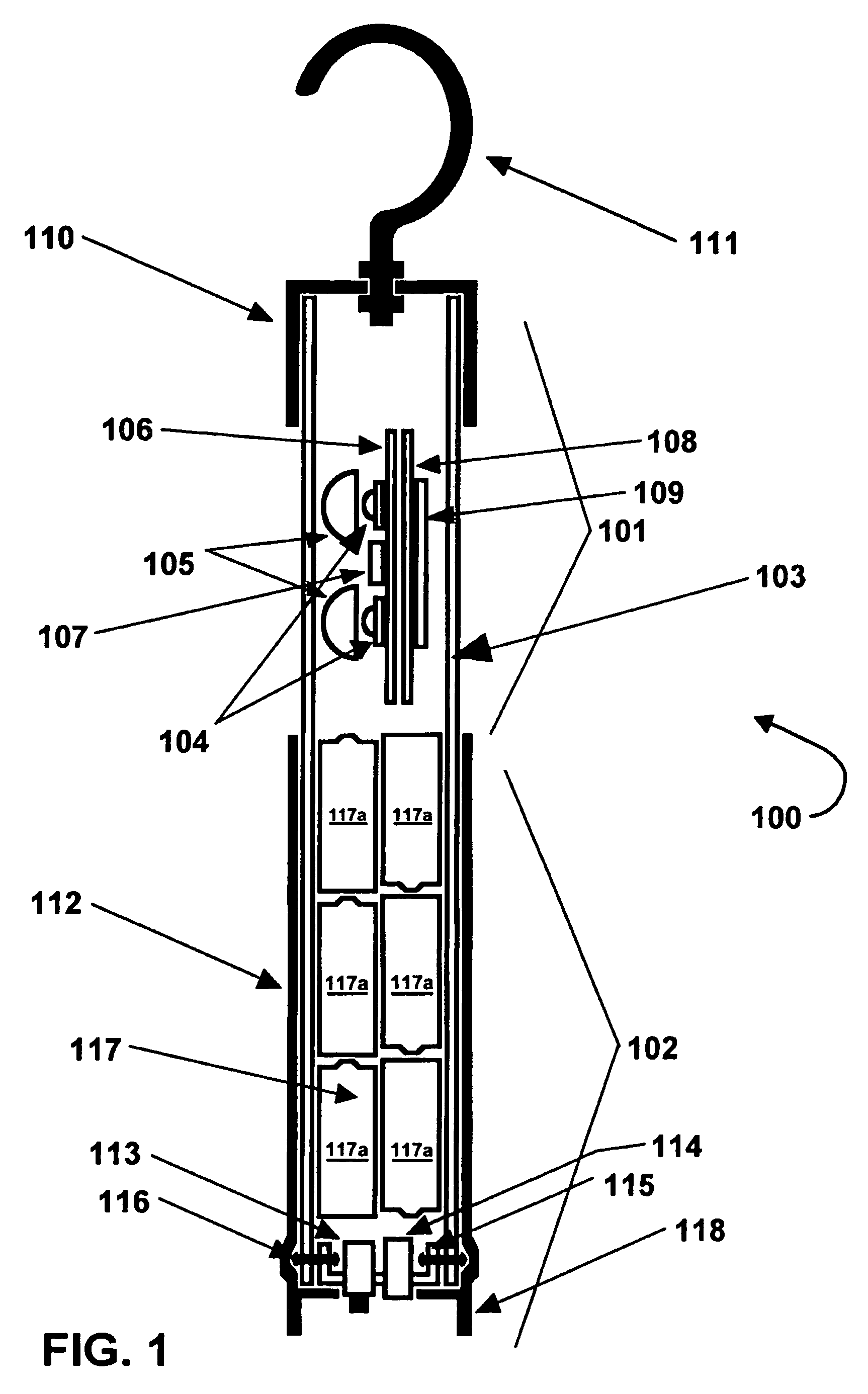
[0062]Referring to FIG. 1, an LED work light 100, has a head section 101 and a handle section 102. The LED work light 100 has a transparent plastic tube 103 as a main structural member, which is common to both the head section 101 and the handle section 102. The plastic tube 103 is preferably polycarbonate but may alternatively be made of a different plastic such as acrylic. Other suitable transparent materials, plastic or non-plastic, may be utilized for the tube 103. The plastic tube 103 may have ridges and / or one or more grooves (not shown) to hold.

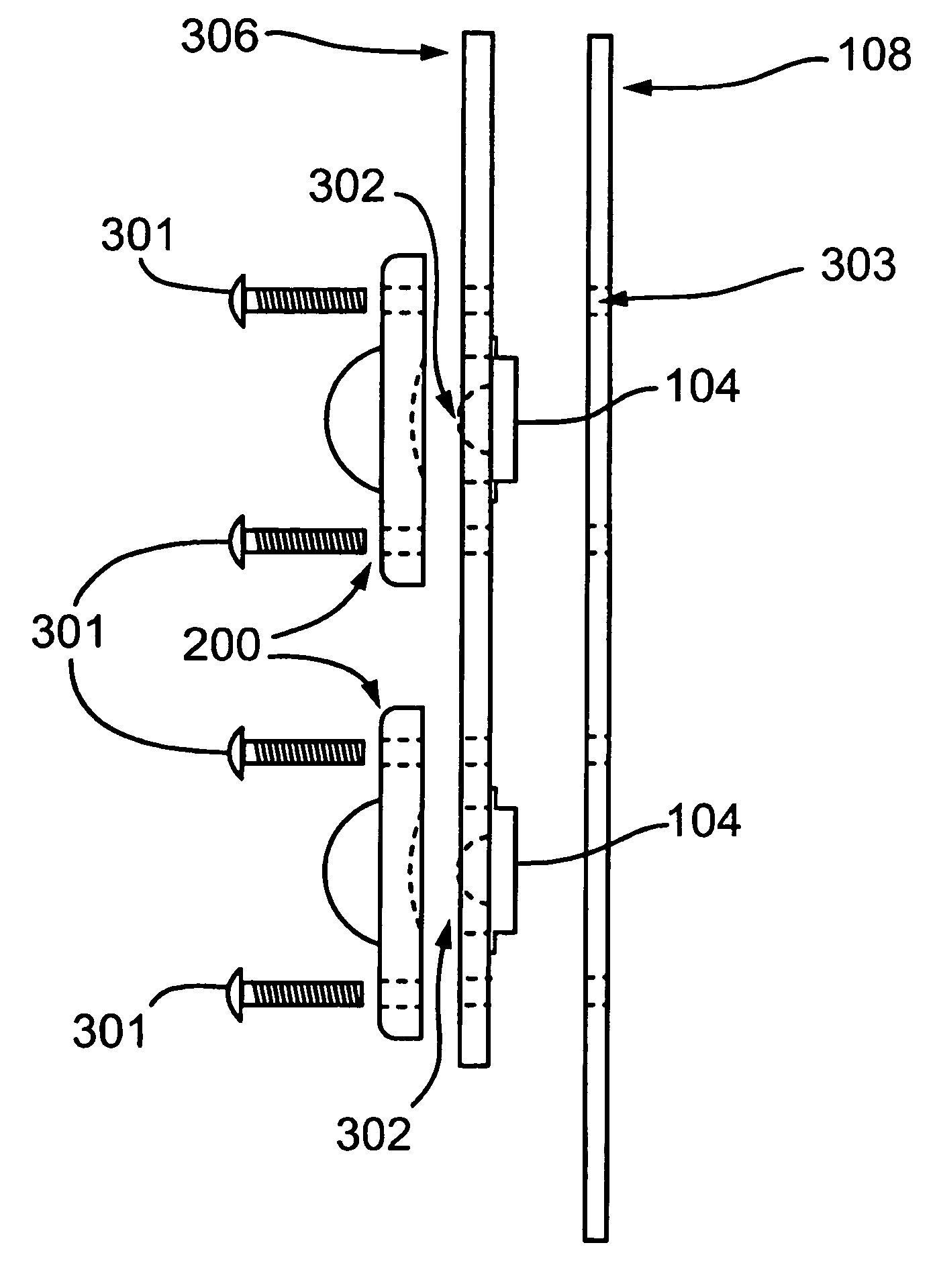
[0063]The LED work light 100 has at least one LED 104. The LED work light 100 is shown as having two LEDs 104, although a different number of LEDs 104 can be used. LEDs 104 are preferably mounted onto an LED board 106. The LED board 106 is preferably also a heatsink and may be made of metal core printed circuit board. Alternatively, an LED board 106 can be made to have useful heatsinking capability by attaching a conventional circuit b...


PUM


Abstract

An LED work light has multichip LEDs and a diffusing dome. Each LED may have separate electrical terminals for each chip. The LED work light may have convex lenses forward of each LED. Convex lenses may be hemispherical. Convex lenses may have a nonhemispheric curved surface whose cross section has at least one circular arc and no non-circular arcs. The LED work light has a battery or receives power from an external power source. The LED work light may have a transparent plastic tube as a structural member. A replaceable plastic cover may be added to protect any structural tube or other major transparent part of the LED work light from abrasions. The plastic cover may be tubular. The plastic cover may comprise laminations of plastic that can be removed individually after being abraded. Any external power source may be a wall transformer type and may have current limiting means. The LEDs may be attached to the rear surface of an LED PCB that is fastened to a heatsink in a manner achieving thermal contact between the rear surfaces of the LEDs and the heatsink. A position sensing switch may be used.

Description

CROSS-REFERENCE TO RELATED APPLICATIONS[0001]This application is a Continuation-in-Part of U.S. patent application Ser. No. 11 / 083,086, entitled LED WORK LIGHT, filed Mar. 18, 2005 which claims the benefit of the filing date of U.S. Provisional Patent Application No. 60 / 521,240 filed Mar. 18, 2004 under the title LED WORK LIGHT, the filing date of U.S. Provisional Patent Application No. 60 / 521,680 filed Jun. 16, 2004 under the title LED WORK LIGHT, the filing date of U.S. Provisional Patent Application No. 60 / 521,689 filed Jun. 17, 2004 under the title LED WORK LIGHT, the filing date of U.S. Provisional Patent Application No. 60 / 521,738 filed Jun. 28, 2004 under the title LED WORK LIGHT and the filing date of U.S. Provisional Patent Application No. 60 / 521,888 filed Jul. 17, 2004 under the title LED WORK LIGHT.[0002]This application is also a US National Stage Application of International Application No. PCT / CA2007 / 000802 filed May 4, 2007 under title LED WORK LIGHT which claims prio...

Claims


Application Information

Patent Timeline
Patent Type & Authority Patents(United States)
IPC IPC(8): F21L4/02
CPCF21L14/023F21Y2101/02F21Y2115/10
Inventor KLIPSTEIN, DONALD L.BRASS, JACKWHITFIELD, ROBERT TOD
Owner ALLTEMP PROD CO LTD
Why Eureka
Try Eureka