
Eccentric rocking type reduction gear

Active Publication Date: 2013-10-22
JTEKT CORP
View PDF16 Cites 3 Cited by
  • Summary
  • Abstract
  • Description
  • Claims
  • Application Information

AI Technical Summary

Benefits of technology

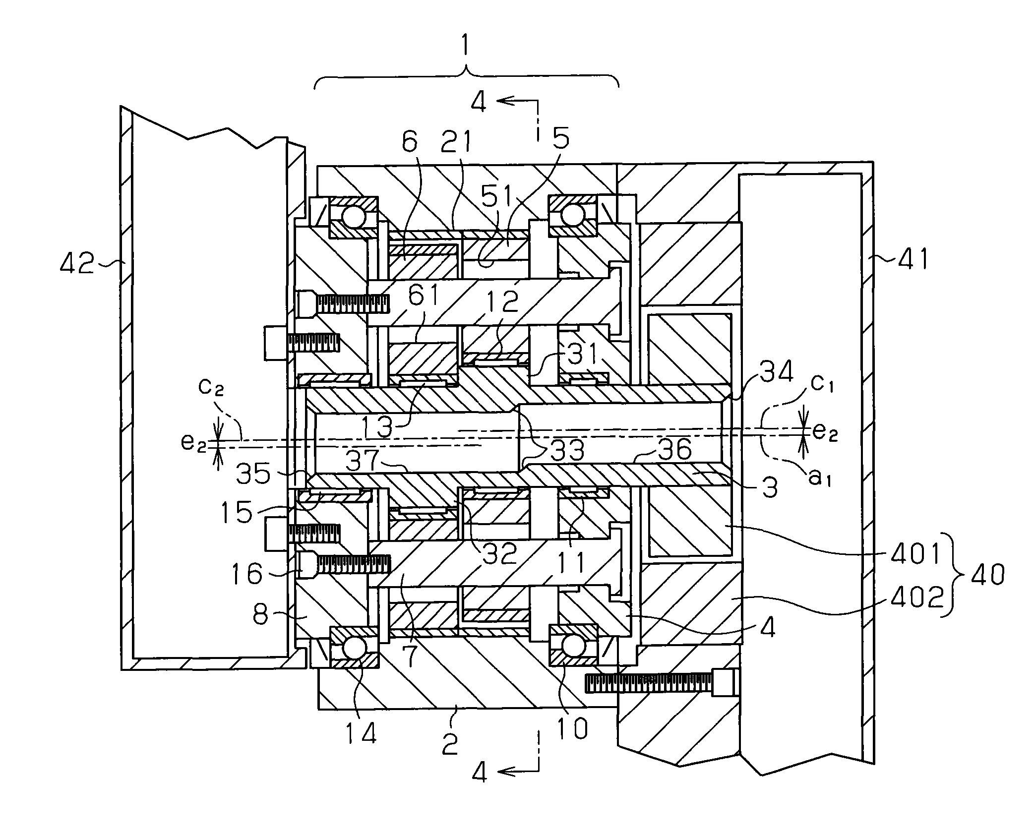
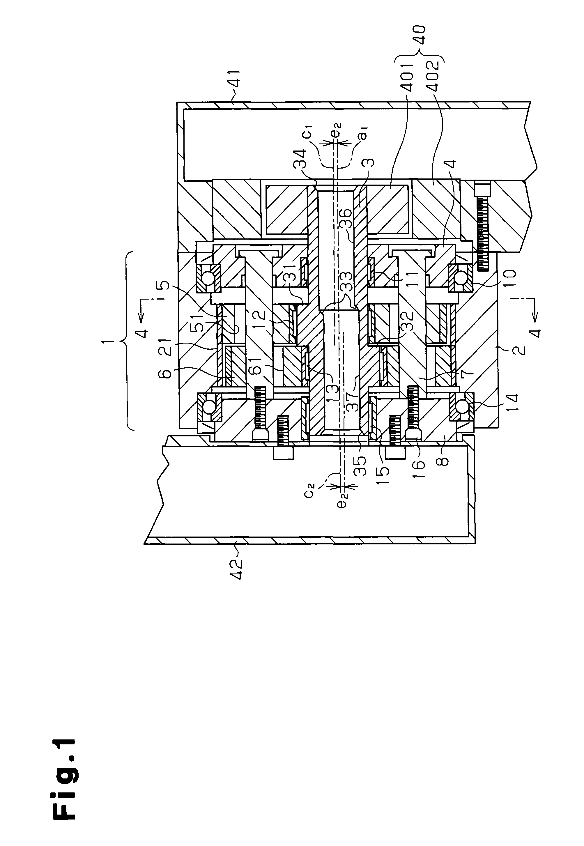
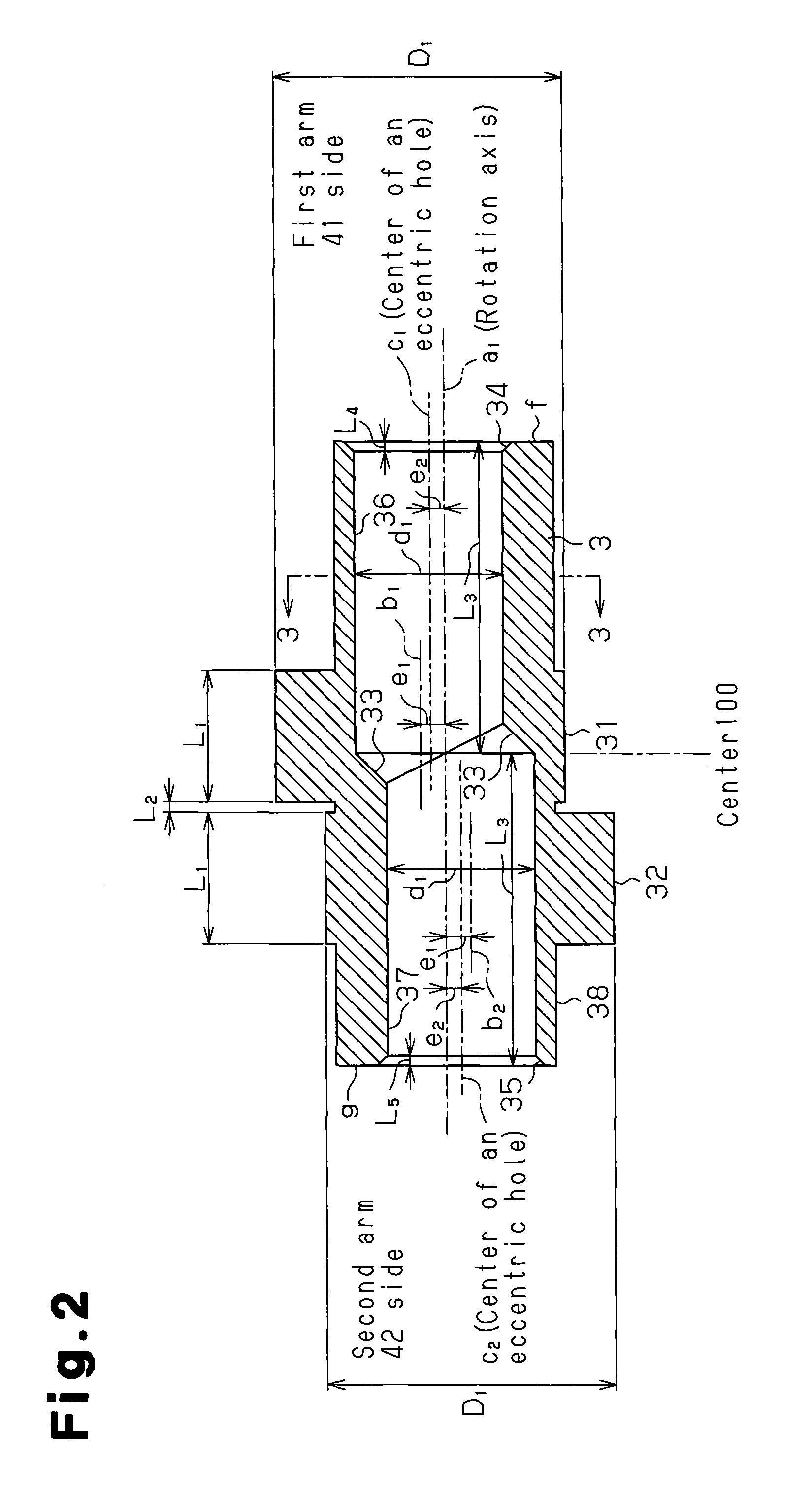
The present invention provides an eccentric rocking type reduction gear that reduces fluctuating load acting on a bearing due to a rotation of a crank shaft to extend the lifetime of the bearing, and which also suppresses a generation of vibration. The first and second cylindrical cams are disposed around the crank shaft with respective phases being shifted from each other by 180 degrees to reduce the translational force due to centrifugal force acting on the crank shaft. The first and second eccentric holes reduce the moment of couple due to the centrifugal force acting on the crank shaft. The axial-end balance adjusting portions are provided at both ends of the crank shaft to adjust the rotation balance of the crank shaft. The chamfering level can be adjusted finely without any special process to achieve the desired rotation balance. The weight of the balancer can be adjusted finely even after the crank shaft is assembled. The reduction of both translational force and moment of couple reduces the fluctuating load acting on the bearing, extending the lifetime of the bearing and reducing vibration. The recesses in the inner periphery of the crank shaft cancel couple acting on the crank shaft, reducing the moment of couple.

Problems solved by technology

Hence, fluctuating load acts on a bearing that supports the crank shaft due to centrifugal force produced inherently to the unbalanced shape of the eccentric cylindrical cam.
However, the unbalance around the axial line orthogonal to the axial line of the crank shaft still remains unaddressed.
This often results in the shortage of the lifetime of the bearing.
Moreover, the eccentric rocking type reduction gear is likely to generate vibration.

Method used


Image

  • Eccentric rocking type reduction gear
  • Eccentric rocking type reduction gear
  • Eccentric rocking type reduction gear

Examples


embodiment

Advantages of Embodiment

[0089]Hence, according to the present embodiment, the following advantages can be accomplished.

[0090](1) The unbalancing of the crank shaft 3 when the crank shaft 3 rotates can be reduced by providing the two eccentric holes 36 and 37. This results in a reduction of the fluctuating load acting on the bearings 11 and 15 supporting the crank shaft 3. Accordingly, the lifetime of the bearing in the reduction gear 1 can be extended. Moreover, an occurrence of vibration of the reduction gear 1 originating from the unbalancing of the crank shaft 3 when it rotates can be also suppressed.

[0091]The value of the unbalancing level when the crank shaft 3 rotates, and thus the value of the fluctuating load acting on the bearings 11 and 15 supporting the crank shaft 3 can be easily suppressed to a value equal to or smaller than a desired value by simply providing the eccentric holes 36 and 37 in the crank shaft 3. Moreover, the lifetime of the bearing in the reduction gear...


PUM


Abstract

A crankshaft has eccentric holes communicating with each other. The eccentric hole extends in the axial direction of the crankshaft from one end surface of the crankshaft and is disposed so as to be eccentric in the same direction as a cam section. The eccentric hole extends in the axial direction of the crankshaft from the other end surface of the crankshaft and is disposed so as to be eccentric in the direction of the eccentricity of a cam section. A centrifugal force due to the rotation of the crankshaft generates a force couple about an axis which is perpendicular to the axis of the crankshaft. The force couple is reduced by the eccentric holes. The cam sections are arranged around the axis of rotation with the phases shifted by 180 degrees from each other. As a result, a translational force acting in the direction perpendicular to the axis of the crankshaft is also reduced.

Description

FIELD OF THE INVENTION[0001]The present invention relates to an eccentric rocking type reduction gear, and more specifically, to an improvement of a rotation balance of a crank shaft that performs eccentric rocking on an external gear of the eccentric rocking type reduction gear.BACKGROUND OF THE INVENTION[0002]Eccentric rocking type reduction gears include a crank shaft. The crank shaft includes an eccentric cylindrical cam in order to perform eccentric rocking on an external gear. In general, the crank shaft is utilized as an input shaft, and rotates at a fast speed. Hence, fluctuating load acts on a bearing that supports the crank shaft due to centrifugal force produced inherently to the unbalanced shape of the eccentric cylindrical cam. For example, according to a reduction gear disclosed in Patent Document 1, in order to reduce such fluctuating load, the eccentric cylindrical cam is formed with a balancer weight. This suppresses the unbalance originating from the weight of the ...

Claims


Application Information

Patent Timeline
IPC IPC(8): F16H1/32
CPCF16H1/32F16H2001/325F16H2001/324F16H2001/328
Inventor SATO, HISATAKAKATOH, YOSHINOBU
Owner JTEKT CORP
Learn More