Method and apparatus for repairing concrete

a concrete and repair method technology, applied in the field of concrete repair methods and equipment, can solve the problems of cracks that can develop in concrete structures, failure of structures, propagation of cracks in the joints between old and new concrete, etc., and achieve the effect of simple implementation and less cos

Active Publication Date: 2013-10-29
GARLAND INDS
View PDF24 Cites 5 Cited by
  • Summary
  • Abstract
  • Description
  • Claims
  • Application Information

AI Technical Summary

Benefits of technology

[0007]The present invention is directed to a method and apparatus for strengthening and repairing concrete connections, and more particularly directed to a method and apparatus for repairing the flange-to-flange connections for precast and prestressed double tee systems. The method or repair of the present invention includes the use of an improved composite material that is bonded to a damaged region of concrete. The method of repair of the present invention is simple to implement, generally less expensive than welding or bolting a supplemental joining apparatus to the damaged concrete, and only requires a small region about the damaged concrete to be closed down for repair, thus minimizing the need to close off the complete concrete structure during the repair process. This last advantage is beneficial to car garage owners since the method of repair of the present invention does not require the car garage to be closed or a level of the car garage to be closed while repairing the damaged regions of the car garage.
[0019]In still another and / or alternative non-limiting aspect of the present invention, a slot is cut into one or more concrete structures or slabs at a nonparallel angle to a gap between the two concrete structures or slabs. Generally, in a structure such as, but not limited to a parking garage, T-shaped beams (e.g., T-shaped concrete beams, etc.) are used to support a plurality of concrete structures or slabs. In such an arrangement, a gap exists between the two concrete structures or slabs. The cut slot of the present invention is cut at a nonparallel angle to such gap and is also cut into the concrete structures or slabs positioned on both sides of the gap. The size, length and depth of the repair cut slot are selected to ensure that the improved composite material is properly inserted into the repair cut slot of the concrete structure or slab. In one non-limiting embodiment of the invention, the angle of the cut slot relative to the gap between the two concrete structures or slabs is about 10°-170°. In one non-limiting aspect of this embodiment, the angle of the cut slot relative to the gap between the two concrete structures or slabs is about 20°-160°. In another non-limiting aspect of this embodiment, the angle of the cut slot relative to the gap between the two concrete structures or slabs is about 30°-150°. In another non-limiting aspect of this embodiment, the angle of the cut slot relative to the gap between the two concrete structures or slabs is about 45°-135°. It has been found that when the angle of the cut slot relative to the gap between the two concrete structures or slabs is about 45°-135°, the full load transfer of the composite material to the concrete is obtained and a very high lateral shear in the joint is also obtained. The 45°-135° angle allows the composite material to handle the forces in tension rather than through thickness shear. Generally, the slot is cut so that the slot is centered between the two concrete structures or slabs; however, this is not required. When more than one slot is cut into the two concrete structures or slabs, the slots can be cut in a parallel or nonparallel relationship to one another. In one non-limiting arrangement, two adjacent positioned slots are cut at + / −30-60°. Such alternating slots allow for the maximum tension transfer to the composite material in the slots.
[0025]The orientation of the fibers in the composite material provide for greater strength.
[0029]The composite material has improved tensile capacity, compressive capacity and shear capacity.
[0033]It is another and / or alternative non-limiting object of the present invention to provide a method and apparatus for repairing concrete that will not corrode over time.
[0035]It is yet another and / or alternative non-limiting object of the present invention to provide a method and apparatus for repairing concrete that minimizes the risk of damaging preexisting concrete during the repair process.

Problems solved by technology

Over time, cracks can develop within concrete structures.
If such cracks are left unrepaired, the cracks can result in failure of the structure.
This is a particular problem for parking garages wherein large loads from vehicles daily travel over the concrete surface.
However, new concrete does not always bond perfectly with the preexisting concrete, thus resulting in the propagation of cracks in the joint between the old and new concrete.
Several disadvantages are associated with these past methods of repair and attachment of newly poured concrete.
For instance, the drilling of multiple holes into the existing concrete is a slow and labor intensive process.
Additionally, the vibrations associated with the drilling of the holes can cause an entire section of concrete to fail.
Furthermore, cracks can form over time in the joint between the new concrete section and the preexisting concrete.
As such, when moisture seeps down these cracks, the metallic reinforcing bars will rust, corrode, and subsequently fail, thereby necessitating further repair of the concrete section.
Such defective bonding can lead to premature failure of the reinforced joint.
The repair of concrete structures such as a parking garage structure, a concrete driveway or the like that is disposed above T-shaped concrete beams can be problematic.
As cracks form in the concrete structures, moisture seeps into the concrete supports and corrodes the metal clips.
Such metal clip corrosion ultimately causes the metal clip to fail, which can result in the collapsing of a concrete slab within the parking garage.
This method is expensive and labor intensive.
Additionally, the repair is aesthetically unappealing.
Again, this process is labor intensive and expensive.

Method used


Image

  • Method and apparatus for repairing concrete
  • Method and apparatus for repairing concrete
  • Method and apparatus for repairing concrete

Examples


Embodiment Construction

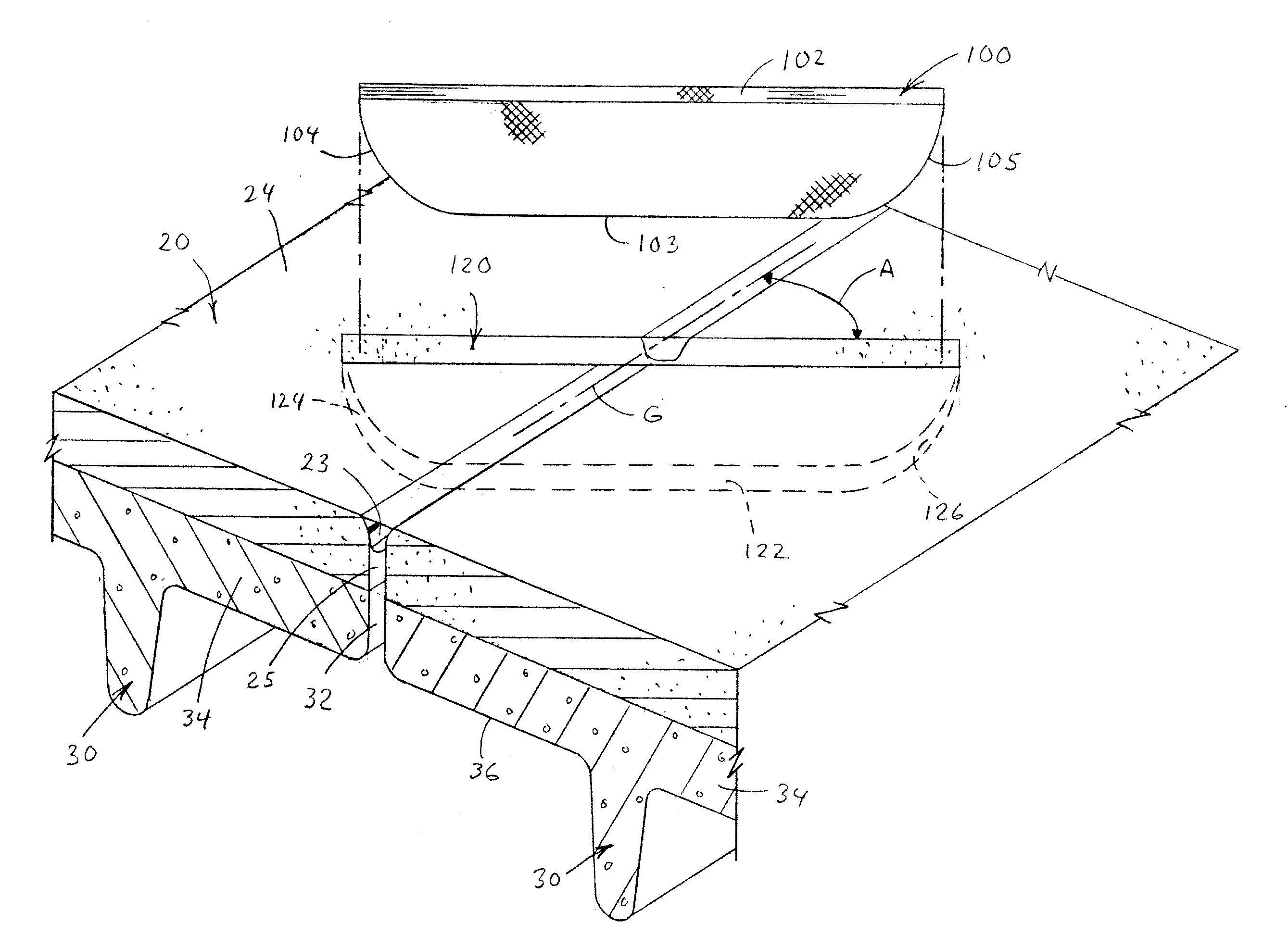
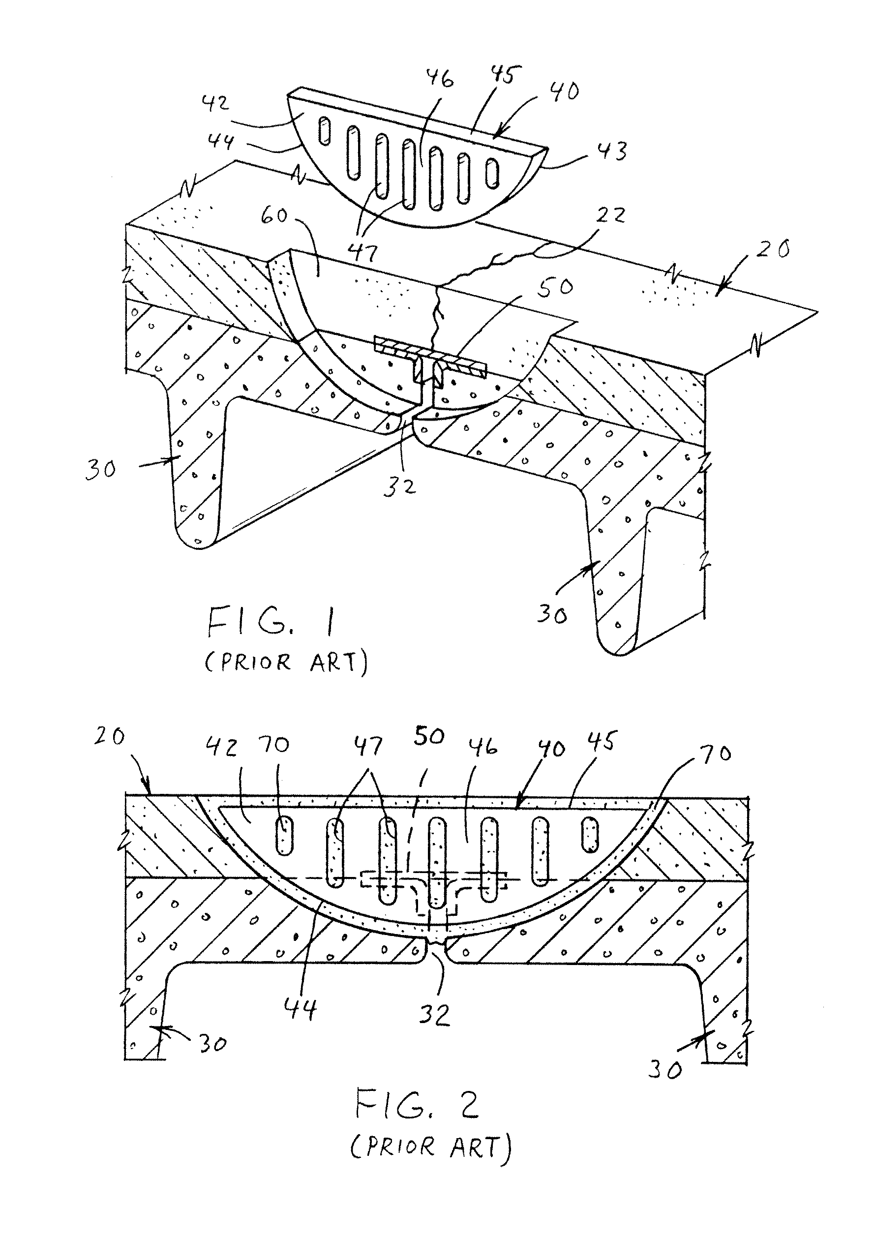
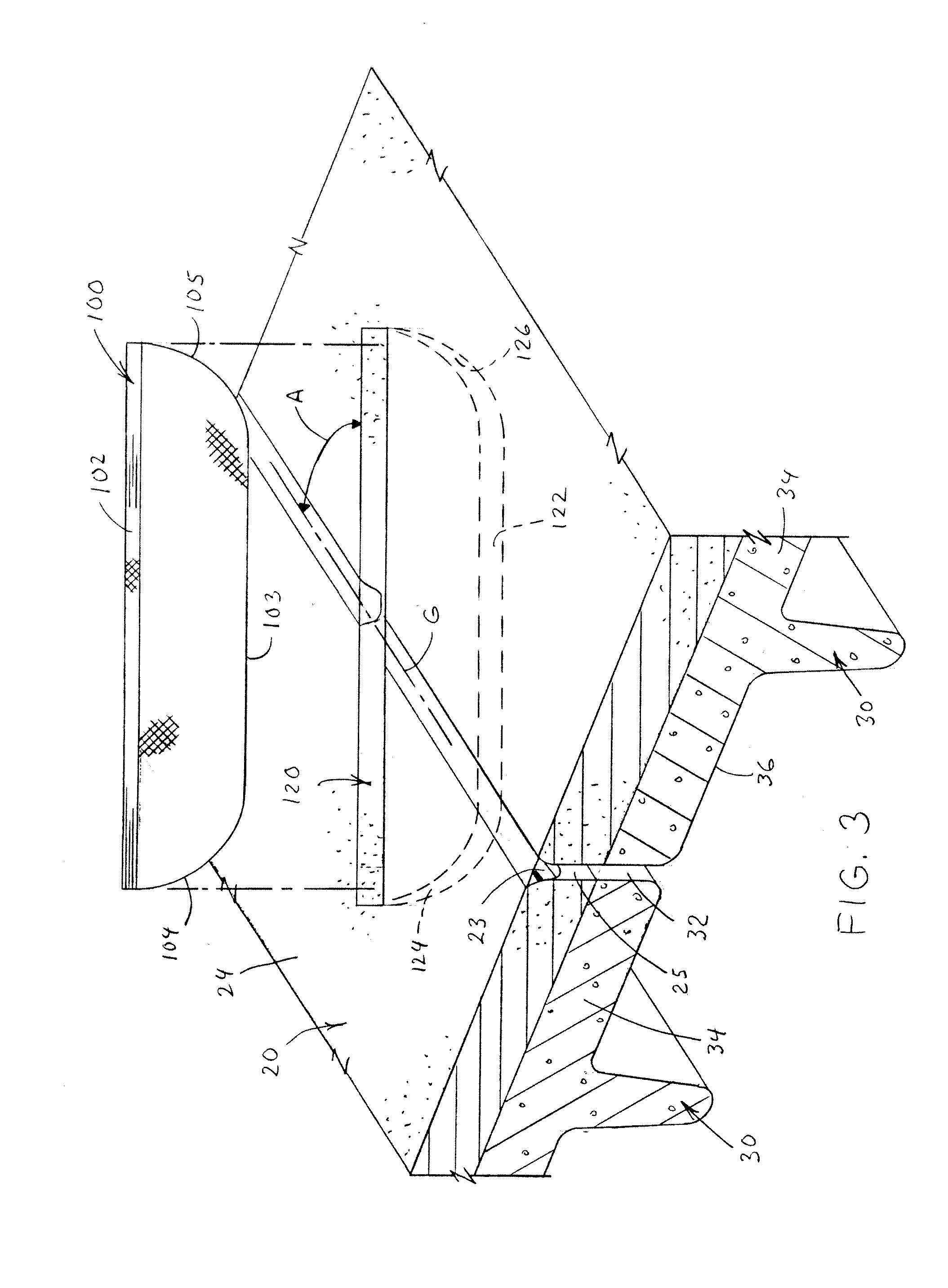
[0046]Referring now to the drawings wherein the showings are for the purpose of illustrating preferred embodiments of the invention only and not for the purpose of limiting same, FIGS. 1 and 2 illustrate a typical concrete deck 20 that is disposed above concrete T-shaped planks 30. A prior art concrete insert 40 as disclosed in U.S. Pat. No. 6,312,541 is illustrated as forming a repair to the damaged concrete deck. The concrete deck is also illustrated as supported by metal clips 50 that join together the concrete T-shaped planks 30. The concrete insert 40 is designed to repair the metal clips 50 that have failed as a result of corrosion from moisture that has seeped into cracks 22 that have formed in concrete deck 20. The concrete insert 40 is illustrated as a relatively thin, elongated oblong-shaped structure having first and second major surfaces 42 and 43, a flat top 45 and an arcuate side or edge 44. Edge 44 is curved. The peripheral shape of edge 44 at least approximates the s...


PUM

PropertyMeasurementUnit
angleaaaaaaaaaa
angleaaaaaaaaaa
angleaaaaaaaaaa

Abstract

A composite material used to repair concrete. The composite material includes a first fiber system including at least one fiber layer. Each fiber layer includes a plurality of fibers. The binding material secures together the plurality of fibers. The composite material is positioned and secured in a slot cut in a concrete structure.

Description

[0001]The present invention is directed to a method and apparatus for strengthening concrete, more particularly directed to a method and apparatus for strengthening and / or repairing concrete connections, and still more particularly directed to a method and apparatus for repairing the flange-to-flange connections for precast and prestressed double tee systems.BACKGROUND OF THE INVENTION[0002]Concrete structures are commonly used for buildings, parking garages and the like. Over time, cracks can develop within concrete structures. If such cracks are left unrepaired, the cracks can result in failure of the structure. This is a particular problem for parking garages wherein large loads from vehicles daily travel over the concrete surface. To prevent the failure of the concrete structure without having to replace the entire concrete structure, the damaged concrete structure is often repaired by cutting the damaged section away from a preexisting concrete section, and then pouring new con...

Claims


Application Information

Patent Timeline
Patent Type & Authority Patents(United States)
IPC IPC(8): E02D37/00
CPCE04G23/0218B32B5/024B32B3/02B32B3/30B32B2419/00E04G2023/0251Y10T428/24479
Inventor HEMPHILL, WILLIAM SCOTT
Owner GARLAND INDS
Why Eureka
Try Eureka