Rotary strut sprinkler

a rotary strut and sprinkler technology, applied in the direction of spraying apparatus, spraying apparatus, movable spraying apparatus, etc., can solve the problems of high seal drag and fluid damage, and achieve the effect of low seal drag, low drive torque, and relatively low available drive torqu

Active Publication Date: 2013-10-29
NELSON IRRIGATION
View PDF13 Cites 18 Cited by
  • Summary
  • Abstract
  • Description
  • Claims
  • Application Information

AI Technical Summary

Benefits of technology

[0008]Another feature of the sprinkler designs disclosed herein relates to the incorporation of a second, independent braking device in the form of a compensating, multi-disc friction brake mechanism to help maintain the rotational speed of the water-deflection plate relatively constant over a wide range of nozzle sizes and line pressure variations. Water striking the water-deflection plate creates an axial load which is transferred by the frame to the housing. With small nozzles and low line pressures, very little axial load is developed by water striking the water-deflection plate. In the nonlimiting embodiments described herein, a wave (or other) spring transfers the axial load to the sprinkler hub and prevents actuation of the disc brake, so that speed is controlled primarily by the rotary damper. As nozzle size and line pressure increase, however, the extra axial load is carried by the brake discs to the brake hub, which, in turn, is locked to the inner stem of the nonrotatable sprinkler body. A first group of static brake discs floats freely axially on the brake hub. The discs are prevented from rotating by cooperating ribs and grooves. A second group of rotating brake discs floats freely axially in the housing, but these discs are caused to rotate with the housing, also by cooperating ribs and grooves. In the exemplary embodiment, the first and second groups of discs are interleaved with each other. It is this interaction of the discs when compressed as line pressure increases that creates the supplemental braking effect. Water flowing through the grooves on the water-deflection plate creates the torque to drive, i.e., rotate, the water-deflection plate. The braking torque generated by the disc brake increases proportionally to the increase in drive torque, thus maintaining the rotation speed of the water-deflection plate relatively constant.
[0009]Another feature of the invention relates to the incorporation of a “dummy” boss symmetrically placed opposite the rotary damper boss or housing. This helps the unit hang straight when mounted on a flexible supply hose, and reduces twisting of the unit when dragging through a crop. The dummy boss also provides a handgrip for torqing the sprinkler unit onto an adapter. In an alternative arrangement, the dummy boss is eliminated and the rotary damper is mounted such that it rotates along with the water-deflection plate. This arrangement has drawbacks in that a much larger portion of the sprinkler is rotating when in operation and as a result, it is easier for external obstacles, such as corn stalks, to stall the rotation. On the other hand, the advantage of this design is that a pair of rotary seals (i.e., the stem seals) are both relatively small in diameter.
[0010]In still another alternative embodiment, the rotary damper is eliminated and the unit is therefore free to rotate at a relatively high whirling speed to facilitate breakup of the stream which, in turn, helps the water infiltrate the soil better in some situations. This design retains the compensating multi-disc friction brake and an associated spring that prevents the disc brake from actuating with small nozzles and low line pressures. The friction brake is advantageous because with small nozzles and low line pressures, the only drag is seal drag and bearing friction. With sufficient drive built into the water-deflection plate, the unit will spin as desired with small nozzles and low pressure, but absent the rotary damper, might spin overly fast with larger nozzles and higher line pressures if not for the multi-disc friction brake.

Problems solved by technology

Damping fluids are typically difficult to keep sealed, however, i.e., the fluid leaks out, and / or may be contaminated by any water that leaks in, necessitating the use of dual-lip seals that stretch tightly over the shaft, creating high seal drag.

Method used


Image

  • Rotary strut sprinkler
  • Rotary strut sprinkler
  • Rotary strut sprinkler

Examples


Embodiment Construction

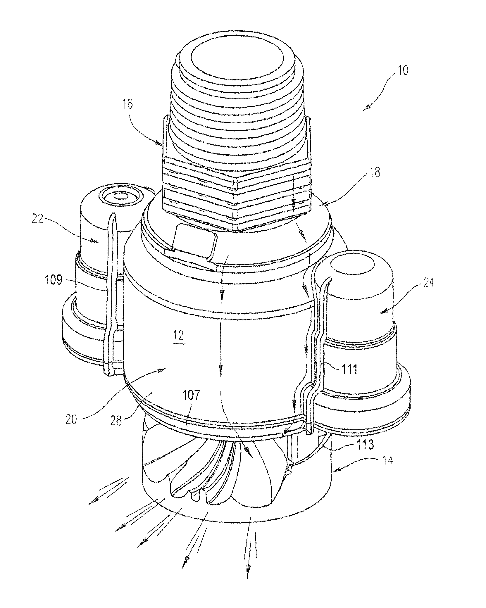
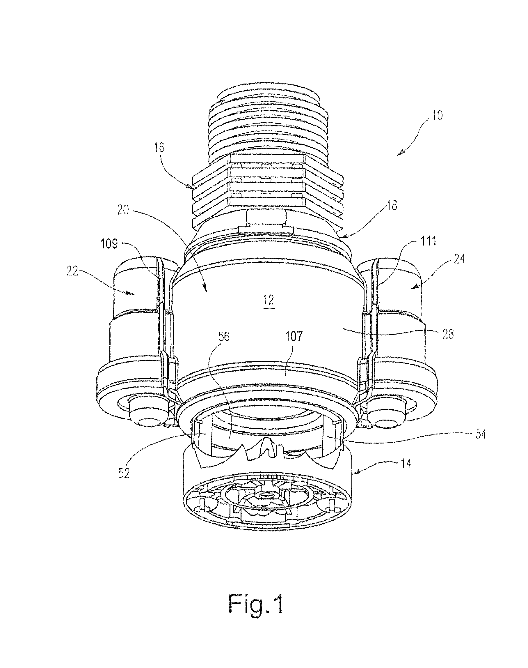
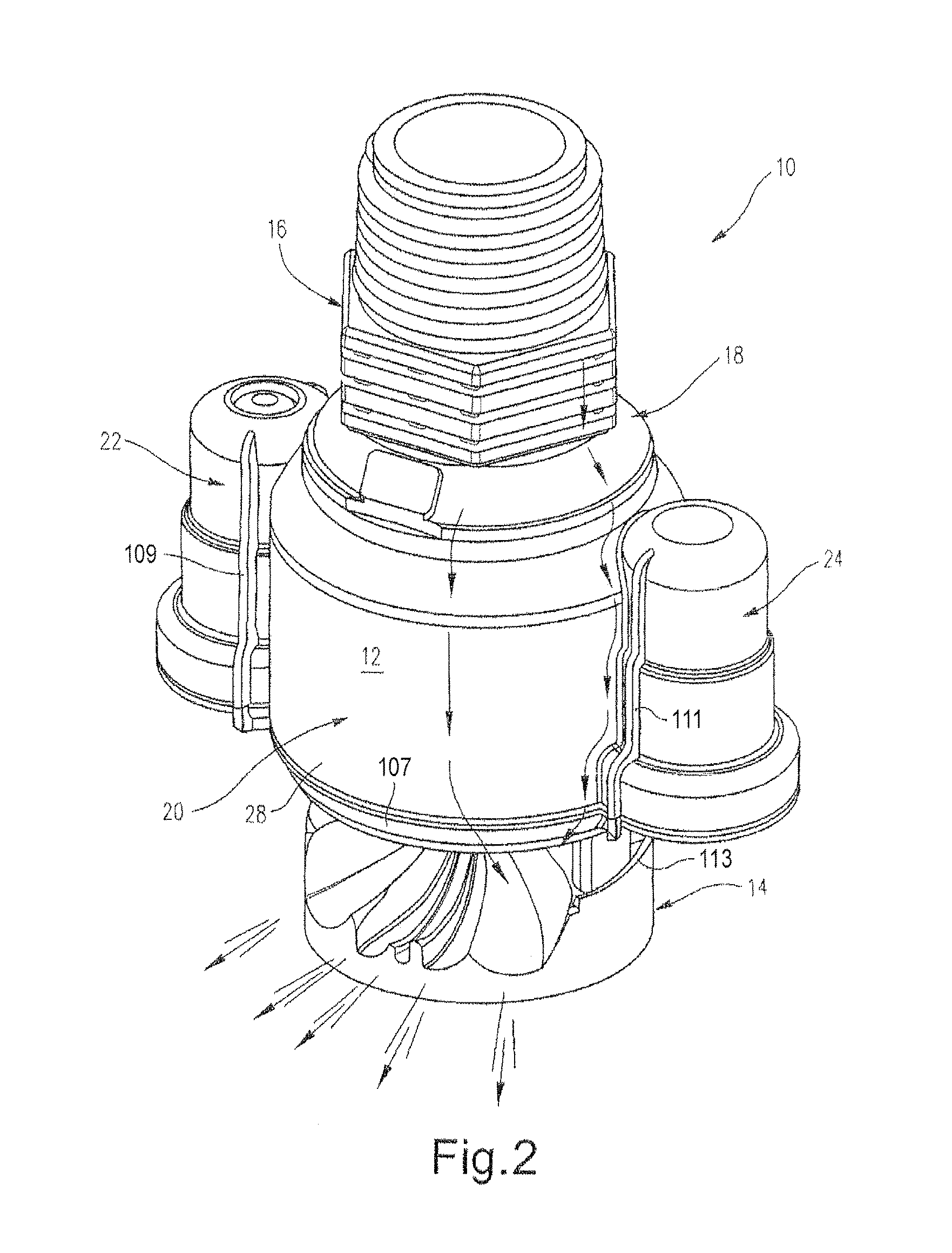
[0032]With reference initially to FIGS. 1 to 3, a sprinkler 10 in accordance with an exemplary and nonlimiting embodiment of this disclosure includes a sprinkler body housing 12 that supports a rotatable water-deflection (or distribution) plate 14 at one end thereof. An adapter 16 is threaded into the sprinkler body at the opposite end thereof, with a replaceable nozzle 18 sandwiched between the adapter and the sprinkler body. The sprinkler body housing 12 includes a substantially cylindrical center body portion 20 and a pair of diametrically opposed, smaller side housings 22 and 24.

[0033]With reference especially to FIG. 3, the center body portion 20 of the sprinkler is formed with an inner cylindrical wall 26, spaced radially and concentrically inwardly of an outer cylindrical wall 28. The inner cylindrical wall 26 is formed with an upper cylindrical wall portion 30 and a lower cylindrical wall portion 32, the lower wall portion 32 having a diameter less than the upper wall portio...


PUM


Abstract

A rotary sprinkler includes a sprinkler body including a nozzle, a water-deflection plate supported for rotational movement relative to the sprinkler body, the water-deflection plate having one or more grooves configured to cause the water-deflection plate to rotate when impinged upon by a stream emitted from the nozzle; a first brake arranged to slow rotation of the water-deflection plate at all times; and a second brake arranged to further slow rotation of the water-deflection plate as a function of water pressure exerted on the water-deflection plate.

Description

[0001]This invention relates generally to sprinklers and, more particularly, to rotary sprinklers with internal braking mechanisms for slowing the speed of rotation of a water-deflection plate that radially disburses a stream emitted from the sprinkler nozzle.BACKGROUND OF THE INVENTION[0002]Rotating sprinklers are often employed on traveling irrigation machines such as center-pivot machines, lateral-move machines, etc. Typically, the sprinklers are attached to the lower end of a rigid water supply pipe (or a flexible water supply hose) descending from a lateral boom on a traveling irrigation machine or from a stationary overhead water manifold as commonly used in greenhouses and riding arenas. One such rotating sprinkler is built around a quick-change nozzle and adapter system as described in U.S. Pat. No. 5,415,348. The rotating sprinkler described in the '348 patent has proven to be reliable and durable, but has drawbacks stemming from the fact that the water exiting the water-de...

Claims


Application Information

Patent Timeline
Patent Type & Authority Patents(United States)
IPC IPC(8): B05B3/02B05B3/06B05B3/04F23D11/04
CPCB05B3/003B05B3/005B05B3/007B05B3/0486
Inventor SESSER, GEORGE L.NELSON, CRAIG B.
Owner NELSON IRRIGATION
Why Eureka
Try Eureka