
Electronic textile

a technology textile tracks, applied in the field of electrically conductive textiles, can solve the problems of poor reliability of the electrically conductive contact between the smd-leds and the electrically conductive textile tracks comprised in the fabric member, and achieve the effect of improving the reliability of the electrically conductive conta

Inactive Publication Date: 2013-10-29
SIGNIFY HLDG BV +1
View PDF8 Cites 61 Cited by
  • Summary
  • Abstract
  • Description
  • Claims
  • Application Information

AI Technical Summary

Benefits of technology

[0007]It is an object of the invention to provide an electronic textile comprising a textile substrate having a substrate electrode, and an electronic component having a component electrode, the component electrode being in electrically conductive contact with the substrate electrode via a coupling layer, wherein the coupling layer comprises a material that enables an improved reliability of the electrically conductive contact.

Problems solved by technology

A drawback of the known electronic textile is a poor reliability of the electrically conductive contact between the SMD-LED's and the electrically conductive textile tracks comprised in the fabric member.

Method used


Image

  • Electronic textile
  • Electronic textile
  • Electronic textile

Examples


Embodiment Construction

[0032]In the following description, the present invention is described with reference to exemplary electronic textiles according to the invention.

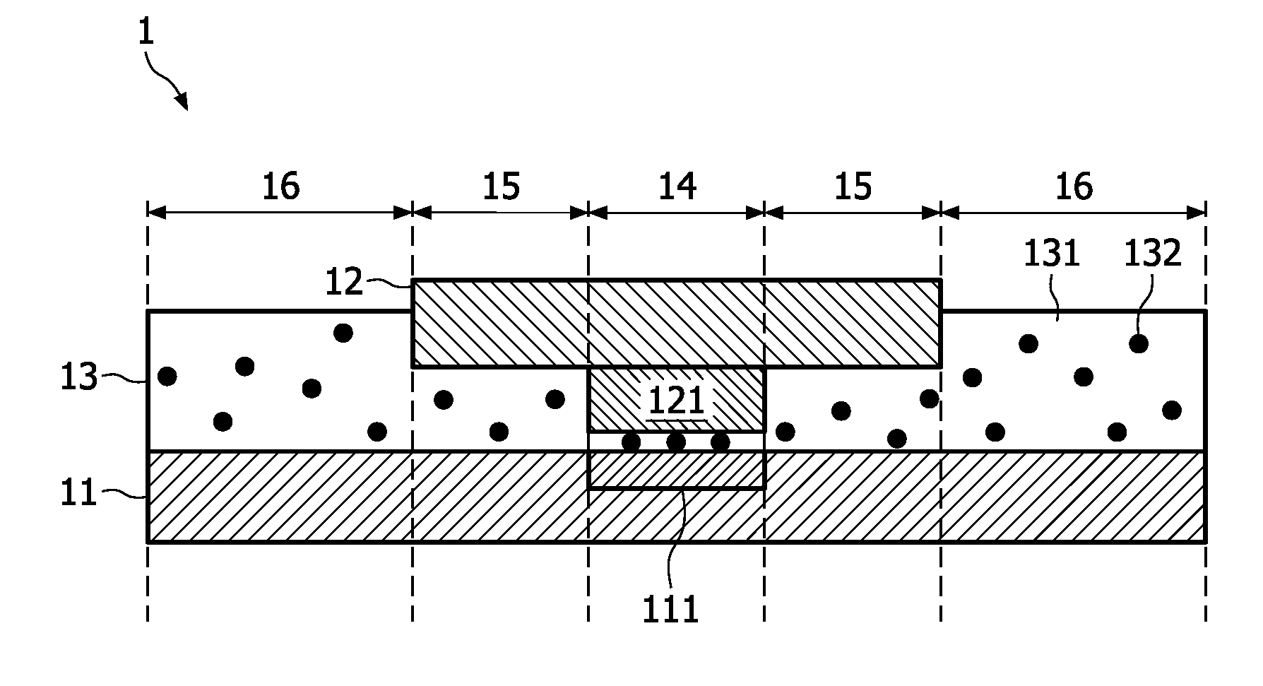
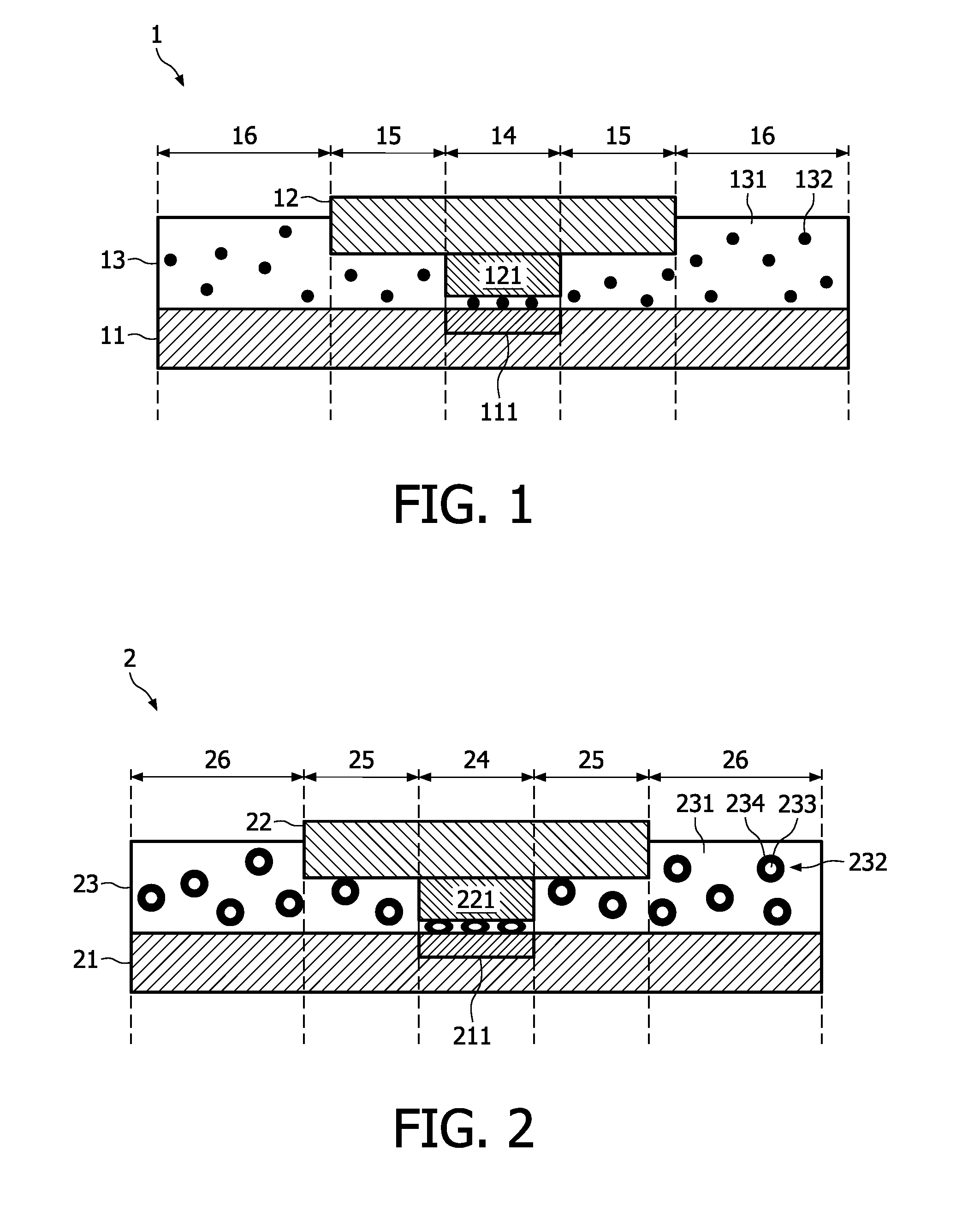
[0033]FIG. 1 shows a schematic cross-section of the electronic textile 1 according to the invention. The electronic textile 1 comprises the textile substrate 11 having the substrate electrode 111, and the electronic component 12 having the component electrode 121. The substrate electrode 111 is connected to the component electrode 121 via the anisotropically conductive material 13.

[0034]Preferably the anisotropically conductive material 13 is applied as a tape, but it can also be applied as a foil, a paste, a grid, or in the form of areas such as strips.

[0035]In FIG. 1, the anisotropically conductive material 13 comprises the electrically insulative binder 131 and electrically conductive particles 132. The electrically insulative binder 131 comprises a thermosetting synthetic resin, and the electrically conductive particles 132 are spheric...


PUM

PropertyMeasurementUnit
diameteraaaaaaaaaa
pressureaaaaaaaaaa
temperatureaaaaaaaaaa

Abstract

The invention relates to an electronic textile comprising a textile substrate having a substrate electrode, and an electronic component having a component electrode. The component electrode is in electrically conductive contact with the substrate electrode via a coupling layer having a directionally dependent conductance so as to preferentially allow an electrical current to flow between the substrate electrode and the component electrode. As the coupling layer does not have to be patterned to prevent the occurrence of parasitic electrical currents, the electrically conductive contact between the substrate electrode and the component electrode has an improved reliability.

Description

FIELD OF THE INVENTION[0001]The invention relates to an electronic textile comprising a textile substrate having a substrate electrode, and an electronic component having a component electrode, the component electrode being in electrically conductive contact with the substrate electrode via a coupling layer.[0002]The invention also relates to a method of manufacturing the electronic textile according to previous paragraph.BACKGROUND OF THE INVENTION[0003]A textile is a material comprised of interlacing fibers, that can for instance be manufactured by weaving, knitting, crocheting, knotting, or pressing fibers together. Many types of textiles are used in our every day life. When electronic components (i.e. devices that work by controlling the flow of electrons) are integrated into a textile new application fields emerge. When the textile is an integral part of the electrical circuit comprising the electronic components, an electronic textile is obtained.[0004]An example of an electro...

Claims


Application Information

Patent Timeline
Patent Type & Authority Patents(United States)
IPC IPC(8): B32B5/16
CPCH05K1/038H05K3/323H05K1/189H05K2201/0233H05K2201/029H05K2201/10393H05K2201/0281Y10T29/49117Y10T442/2008Y10T442/2041Y10T442/2098Y10T442/2107Y10T442/2123Y10T442/2738H05K1/03
Inventor BHATTACHARYA, RABINVAN PIETERSON, LIESBETHVAN OS, KOENSCHULER, THOMASLAMERICHS, GUIDOALTEWISCHER, ERWIN
Owner SIGNIFY HLDG BV
Learn More