Non-contact phase identification method and apparatus

a phase identification and non-contact technology, applied in the direction of phase sequence/synchronization indication, noise figure or signal-to-noise ratio measurement, instruments, etc., can solve the problems of difficult and time-consuming, difficult to move the phase identification instrument, and nearly impossible to hold it in position next to a high overhead cable, so as to reduce the phase shift through the amplifier and achieve high signal level

Active Publication Date: 2013-10-29
PIESINGER GREGORY HUBERT
View PDF5 Cites 5 Cited by
  • Summary
  • Abstract
  • Description
  • Claims
  • Application Information

AI Technical Summary

Benefits of technology

[0013]It is a further object of the present invention to implement the front end amplifier so as to minimize the phase shift through the amplifier as a function of signal dynamic range. This allows the same handheld instrument to be used in ground level high voltage cabinets and in substations where close proximity to high voltage conductors result in high signal levels.
[0014]It is a further object of the present invention to implement a handheld phase identification instrument that can be used by lower-labor-cost non-linemen personnel by eliminating the need for close or direct phase identification instrument contact with the energized conductor.

Problems solved by technology

Maneuvering the phase identification instrument, on the end of a long extendo stick, into position is difficult and time consuming.
It is especially difficult in a strong wind because long extendo sticks are not very rigid.
Gusting winds can cause the phase identification instrument to sway wildly making it nearly impossible to hold it into position next to a high overhead cable.
However, even using short hot sticks is inconvenient because it takes time to attach the phase identification instrument to the stick and hot sticks have to be carefully stored and maintained to remain effective as an insulator.

Method used


Image

  • Non-contact phase identification method and apparatus
  • Non-contact phase identification method and apparatus
  • Non-contact phase identification method and apparatus

Examples


Embodiment Construction

[0042]Commonly owned U.S. Pat. No. 6,667,610 issued Dec. 23, 2003 and U.S. Pat. No. 7,031,859 issued Apr. 18, 2006, which are incorporated herein by reference, describe a non-real-time phase identification system. Commonly owned patent application Ser. No. 12 / 927,767 filed Nov. 23, 2010, which is also incorporated herein by reference, describes a real-time phase identification system.

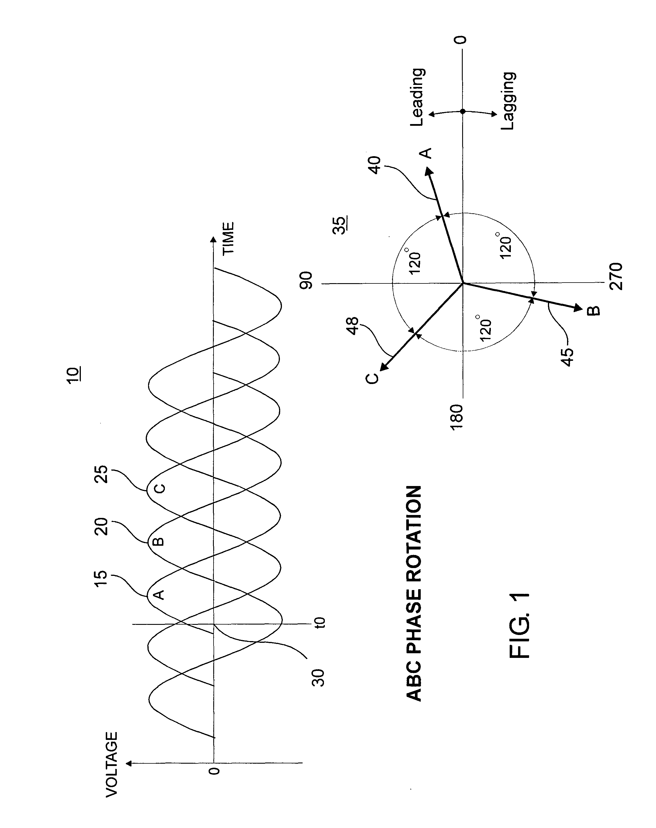
[0043]The basic concept of three-phase powerline voltage with ABC phase rotation is illustrated in FIG. 1. Voltage-time waveform 10 and rotational vector diagram 35 illustrate voltage-time waveform 10 at instantaneous time t0 30. Attribute B voltage 20 and vector 45 lags attribute A voltage 15 and vector 40 by 120 degrees. Likewise, attribute C voltage 25 and vector 48 lags attribute B voltage 20 and vector 45 by 120 degrees.

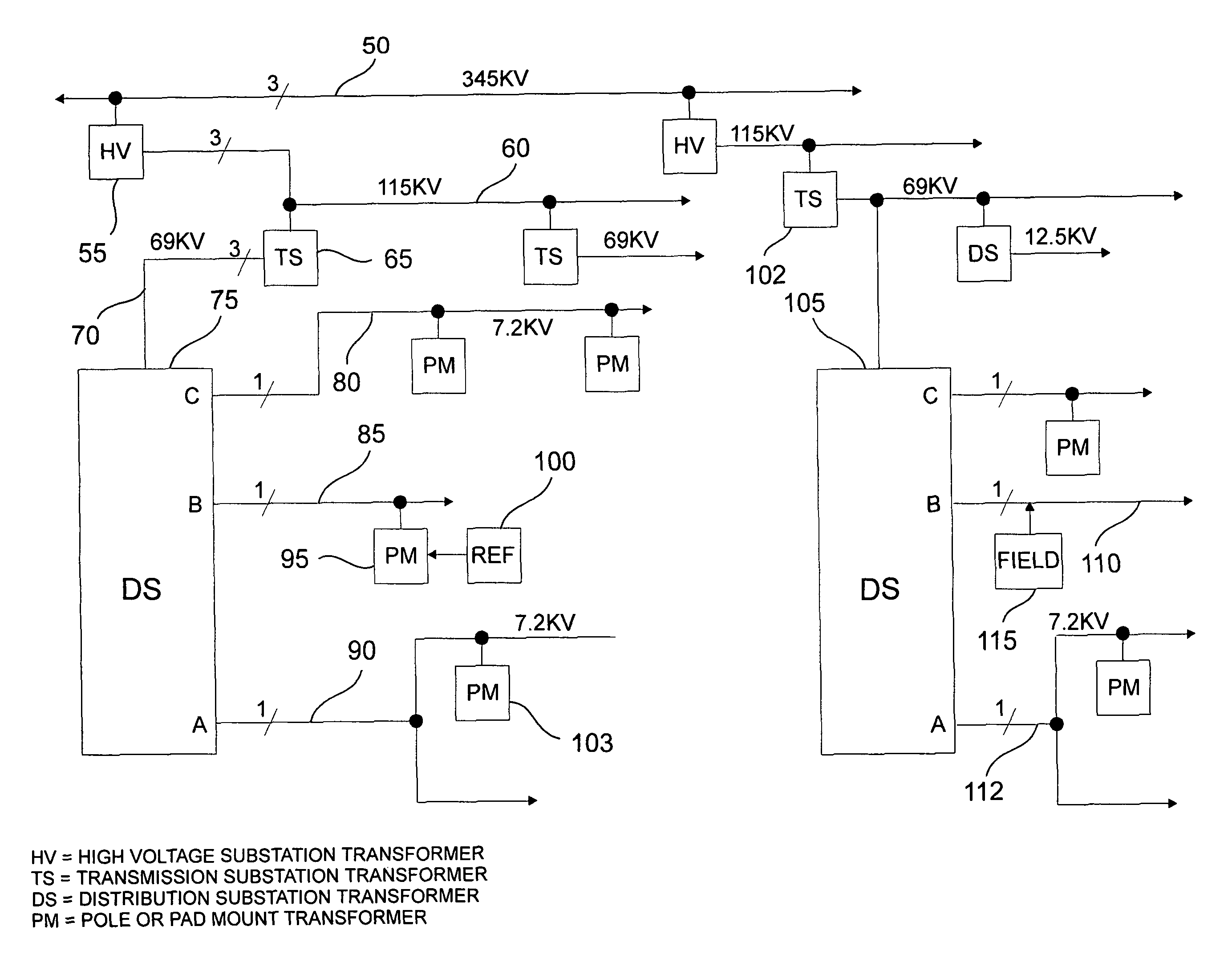
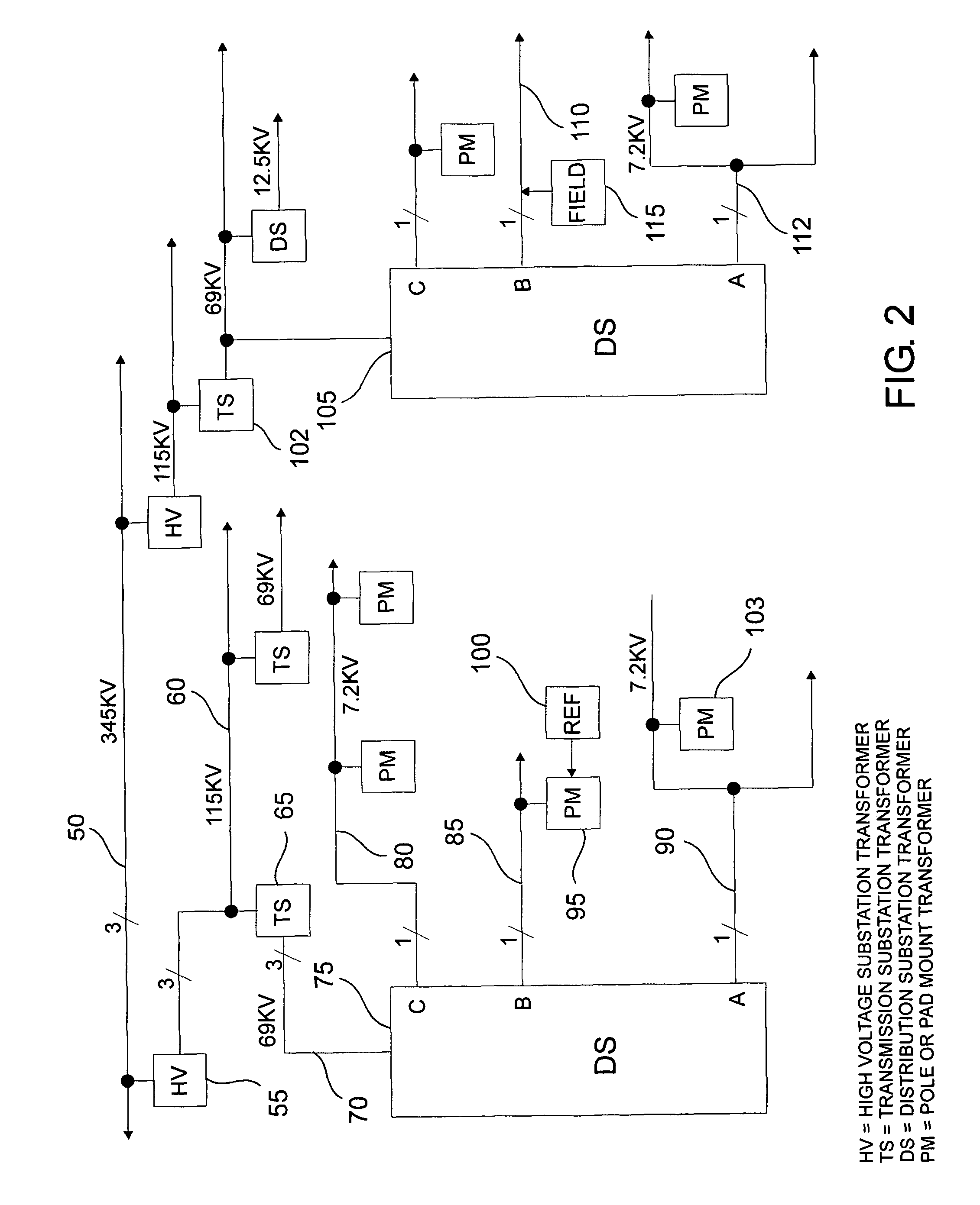
[0044]A typical power distribution network is illustrated in FIG. 2 in which three-phase power cables 50 at 345 KV feed a series of high voltage (HV) transformers 55 spread out over...


PUM


Abstract

A phase identification system identifies the unknown phase attribute of any energized conductor within a three-phase power distribution network by comparing remote location non-contact phase identification instrument phase measurements to phase measurements taken at a reference location. The vector sum of three-phase conductor voltages at the remote measurement location are used to determine the near, center, and far conductor phase attributes of the three-phase lines being measured. This allows phase attributes of high overhead conductors to be determined from ground level using a non-contact handheld instrument.

Description

RELATED INVENTION[0001]The present invention claims priority under 35 U.S.C. §119(e) to: “Non-Contact Phase Identification Method and Apparatus” Provisional U.S. Patent Application Ser. No. 61 / 338,910, filed 24 Feb. 2010 which is incorporated by reference herein.TECHNICAL FIELD OF THE INVENTION[0002]The present invention relates to the field of three-phase power distribution networks. More specifically, the present invention relates to the field of identifying the phase of a conductor in a three-phase power distribution network.BACKGROUND OF THE INVENTION[0003]Electric power distribution networks are used by the electric utilities to deliver electricity from generating plants to customers. Although the actual distribution voltages will vary from utility to utility, in a typical network, three-phase power at high voltage 345,000 volts phase-to-phase (345 KV) is delivered to multiple high voltage substations at which trans-formers step this high voltage down to a lower three-phase vol...

Claims


Application Information

Patent Timeline
Patent Type & Authority Patents(United States)
IPC IPC(8): G01R19/00
CPCG01R29/18
Inventor PIESINGER, GREGORY HUBERT
Owner PIESINGER GREGORY HUBERT
Why Eureka
Try Eureka