Methods and systems for characterization of an anomaly using infrared flash thermography

a technology of infrared flash thermography and anomaly detection, applied in the field of non-destructive evaluation, can solve problems such as differences between two width measurements

Active Publication Date: 2013-11-05
NASA
View PDF23 Cites 53 Cited by
  • Summary
  • Abstract
  • Description
  • Claims
  • Application Information

AI Technical Summary

Benefits of technology

[0011]Another method known as “half-max edge detection” complements the IR Contrast EFBH (or EUG) width predictions, and the reverse is also true. The difference in the two width measurements is considered to be due to non-uniformity of the gap thickness, value of gap thickness, and length effect as well as to the limitations of the two estimations. The e

Problems solved by technology

The difference in the two width measurements is considered to be due to non-uniformity of the gap thic

Method used


Image

  • Methods and systems for characterization of an anomaly using infrared flash thermography
  • Methods and systems for characterization of an anomaly using infrared flash thermography
  • Methods and systems for characterization of an anomaly using infrared flash thermography

Examples


Embodiment Construction

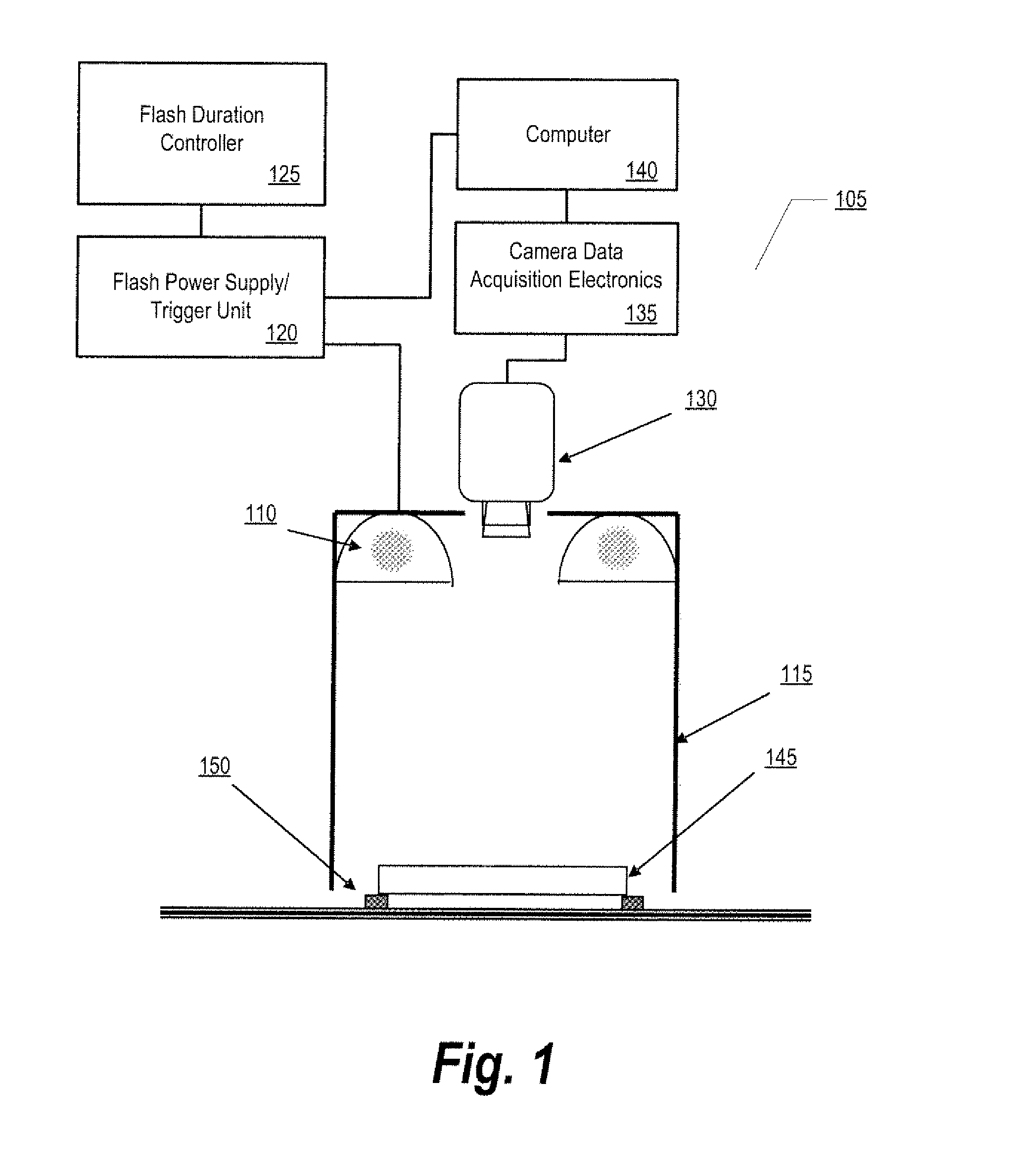
[0050]The objects in the drawings are not necessarily to scale and certain features may be shown exaggerated in scale or in somewhat generalized or schematic form in the interest of clarity and conciseness. In the description which follows like parts may be marked throughout the specification and drawings with the same reference numerals. The foregoing brief description of the drawings is provided for a more complete understanding thereof. It should be understood, however, that the embodiments described are not limited to the precise arrangements and configurations shown. Although the design and use of various embodiments are discussed in detail below, it should be appreciated that the embodiments described represent concepts that may be embodied in a wide variety of contexts. The specific aspects and embodiments described herein are merely illustrative, for it would be impossible or impractical to include all of the possible embodiments and contexts in this detailed description. Up...


PUM


Abstract

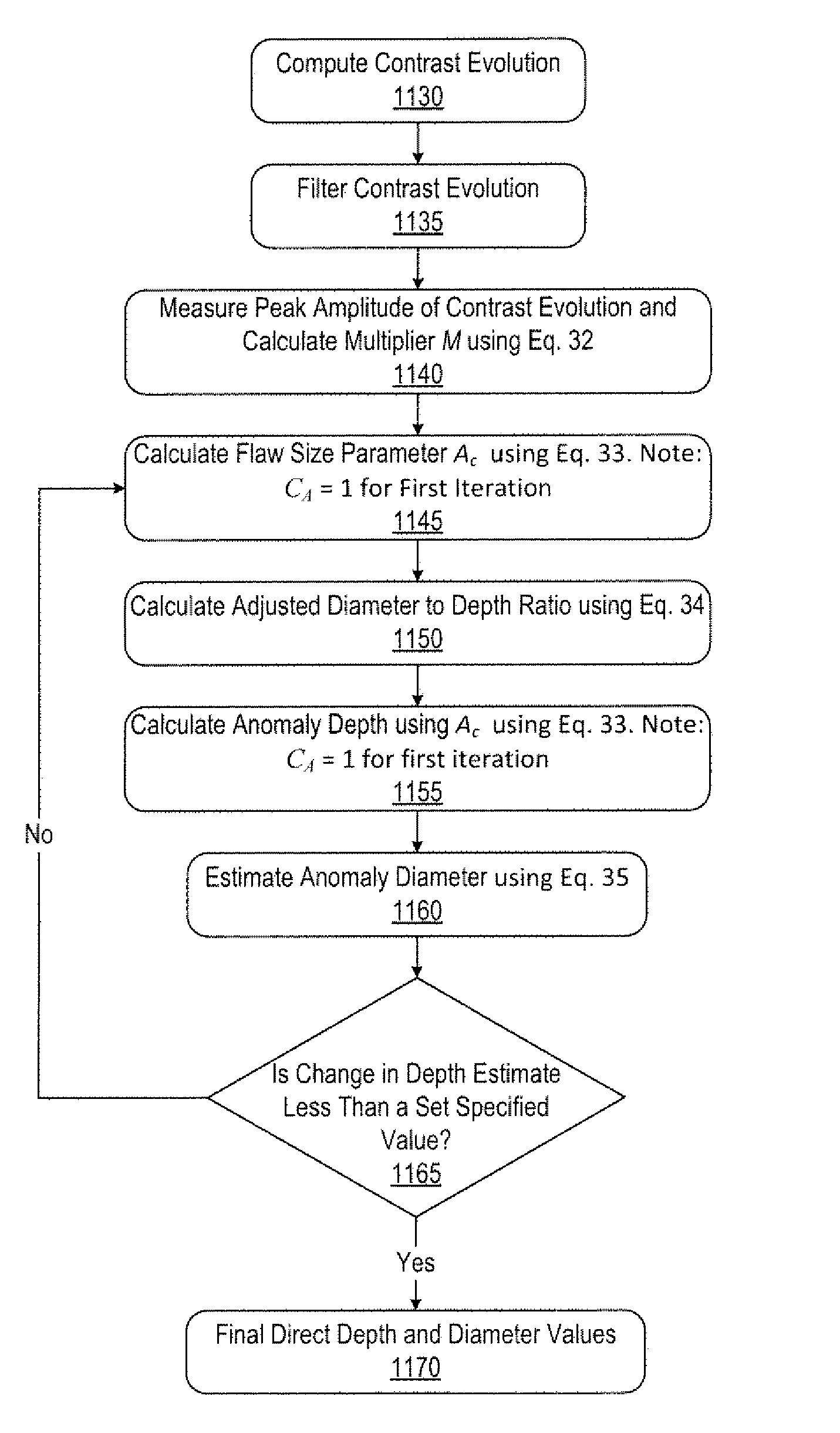
A method for characterizing an anomaly in a material comprises (a) extracting contrast data; (b) measuring a contrast evolution; (c) filtering the contrast evolution; (d) measuring a peak amplitude of the contrast evolution; (d) determining a diameter and a depth of the anomaly, and (e) repeating the step of determining the diameter and the depth of the anomaly until a change in the estimate of the depth is less than a set value. The step of determining the diameter and the depth of the anomaly comprises estimating the depth using a diameter constant CD equal to one for the first iteration of determining the diameter and the depth; estimating the diameter; and comparing the estimate of the depth of the anomaly after each iteration of estimating to the prior estimate of the depth to calculate the change in the estimate of the depth of the anomaly.

Description

I. CROSS REFERENCE TO RELATED APPLICATIONS[0001]This application claims the benefit of the filing date of U.S. provisional patent application No. 61 / 258,266, incorporated herein by reference, which was filed on Nov. 5, 2009, by the same inventor of this application.II. ORIGIN OF THE INVENTION[0002]The invention described herein was made by an employee of the United States Government and may be manufactured and used by or for the Government of the United States of America for governmental purposes without the payment of any royalties thereon or therefor.III. FIELD OF THE INVENTION[0003]The present invention generally relates to the field of non-destructive evaluation (NDE) and of processing of data acquired from a system performing NDE. More particularly, the invention relates to methods and systems for analyzing and processing digital data comprising a plurality of infrared (IR) video images acquired by a system used for non-destructive evaluation.IV. BACKGROUND OF THE INVENTION[000...

Claims


Application Information

Patent Timeline
IPC IPC(8): G06K9/00
CPCG06T7/0004G06T7/602G06T2207/10016G06T2207/10048G06T7/62
Inventor KOSHTI, AJAY M.
Owner NASA
Why Eureka
Try Eureka