Hauling shroud for hauling fibre optic cable along a conduit

a technology of hauling shroud and fibre optic cable, which is applied in the direction of electric cable installation, cable installation apparatus, instruments, etc., can solve the problems of affecting the transmission characteristics of fibre optic cables, the whole process becomes potentially far more complicated, and the fibre optic cable cannot be tied to a hauling rop

Active Publication Date: 2013-11-05
PRYSMIAN AUSTRALIA
View PDF15 Cites 28 Cited by
  • Summary
  • Abstract
  • Description
  • Claims
  • Application Information

AI Technical Summary

Benefits of technology

[0027]The Applicant has found that the overall dimensions of a hauling shroud, which is suitable for receiving a pre-connectorized fibre optic cable thereinto, can be advantageously reduced—in comparison with the overall dimensions of the solutions already known in the art and described herein above—by securing a cable strengthening element directly inside the hauling shroud.
[0042]Preferably, the external surface of the hauling shroud of the present invention has a streamlined shape for assisting in hauling the shroud through the conduit.
[0048]The present invention allows that an optic termination is connected to the fibre optic cable directly in the factory. This provides the significant benefit that the optic termination is associated to the optical fibre(s) in a controlled environment, where access to the cable is relatively easy and appropriate machinery is available to fit, machine, polish and test the optic termination before the cable assembly is sent out for installation.
[0049]Moreover, according to the present invention the hauling shroud can be coupled to and decoupled from a pre-connectorized fibre optic cable by low skilled technical personnel, thereby advantageously decreasing the overall hauling / installation time of the pre-connectorized fibre optic cable.
[0051]Preferably, the cable termination of the present invention comprises an optic connector. In other words, according to a preferred embodiment of the present invention, the hauling shroud is provided with a seat that is suitable for positioning an optic connector, i.e. an assembly comprising a ferrule and a retaining member for housing said ferrule. Therefore, according to this preferred embodiment the cable termination allows that a complete optic connector is housed within the hauling shroud and hauled along a conduit, even though of small internal diameter and provided with bends. According to this preferred embodiment, once the pre-connectorized cable has been hauled along a conduit, the pre-connectorized cable can be connected to an optical device or to a further pre-connectorized cable by simply removing the hauling shroud and engaging the optic connectors, without the need of carrying out any further processing step on the pre-connectorized cable. Therefore, the cable termination according to the present invention allows that the pre-connectorized cable is hauled along conduits of very small dimensions and provided with bends without damage to the connector and, moreover, conferring protection against mechanical stress and environmental factors (principally dirt and moisture) during hauling, storage and handling of the pre-connectorized cable. Furthermore, the system of the present invention also advantageously allows that low skilled technical personnel is employed for the hauling process and the successive step of making the optic network connection.
[0054]According to a preferred embodiment of the present invention, the fibre optic cable is provided with at least two strengthening elements which are associated together to form a loop that removably engages with at least one anchoring member of the hauling shroud. According to this solution the pre-connectorized cable can be easily and quickly decoupled from the hauling shroud without requiring that complex and time consuming operations are requested to be performed on the hauling shroud and / or the pre-connectorized cable by skilled technical personnel.

Problems solved by technology

With the move to fibre optic systems the whole process becomes potentially far more complicated.
While the fibre optic cable, and in particular the fibre, is very flexible, the fibre optic cable cannot be tied to a hauling rope without fracturing the fibre or, at best, severely affecting the fibre's transmission characteristics.
Based on presently known technology, it is expensive and complicated to fit a connector to a fibre optic cable in the field since the mating components of the connector have to be machined after fitting to the fibre to ensure perfect alignment.
Principally, these problems include:(i) Presently known optical lead-in cables do not lend themselves to traditional installation methods since they cannot be hauled in the conventional way.(ii) Connection of the optical lead-in cable to the ONT is relatively complicated.(iii) The use of fusion splicing to connect to the ONT requires highly trained operators with complicated and expensive equipment that is not easily portable to the various locations where the splice is required.(iv) It is not easily possible to fit optical connectors with the required level of performance in the field.(v) The conduit from the distribution point to a customer's premises is small, often being about 20 mm in diameter, and the conduit is not straight in most installations.(vi) The development of a new estate is typically ad hoc in that, once the sub-divisions are approved, the infrastructure services are then installed.
The Applicant has perceived that such a concentric multi-layered structure contributes in increasing the hauling shroud size in the radial direction, thereby negatively affecting—and sometimes even preventing—a correct and effective pulling of a pre-connectorized cable along a conduit, in particular when the latter has a very small inner diameter (e.g. even lower than 20 mm) and is provided with bends (having a curvature radius even down to about 100 mm) along the longitudinal development thereof.

Method used


Image

  • Hauling shroud for hauling fibre optic cable along a conduit
  • Hauling shroud for hauling fibre optic cable along a conduit
  • Hauling shroud for hauling fibre optic cable along a conduit

Examples


Embodiment Construction

[0093]The following modes, given by way of example only, are described in order to provide a more precise understanding of the subject matter of the present invention.

[0094]In the figures, incorporated to illustrate some features of the embodiments of the present invention, like reference numerals are used to identify like parts throughout the figures.

Fibre Optic Cable:

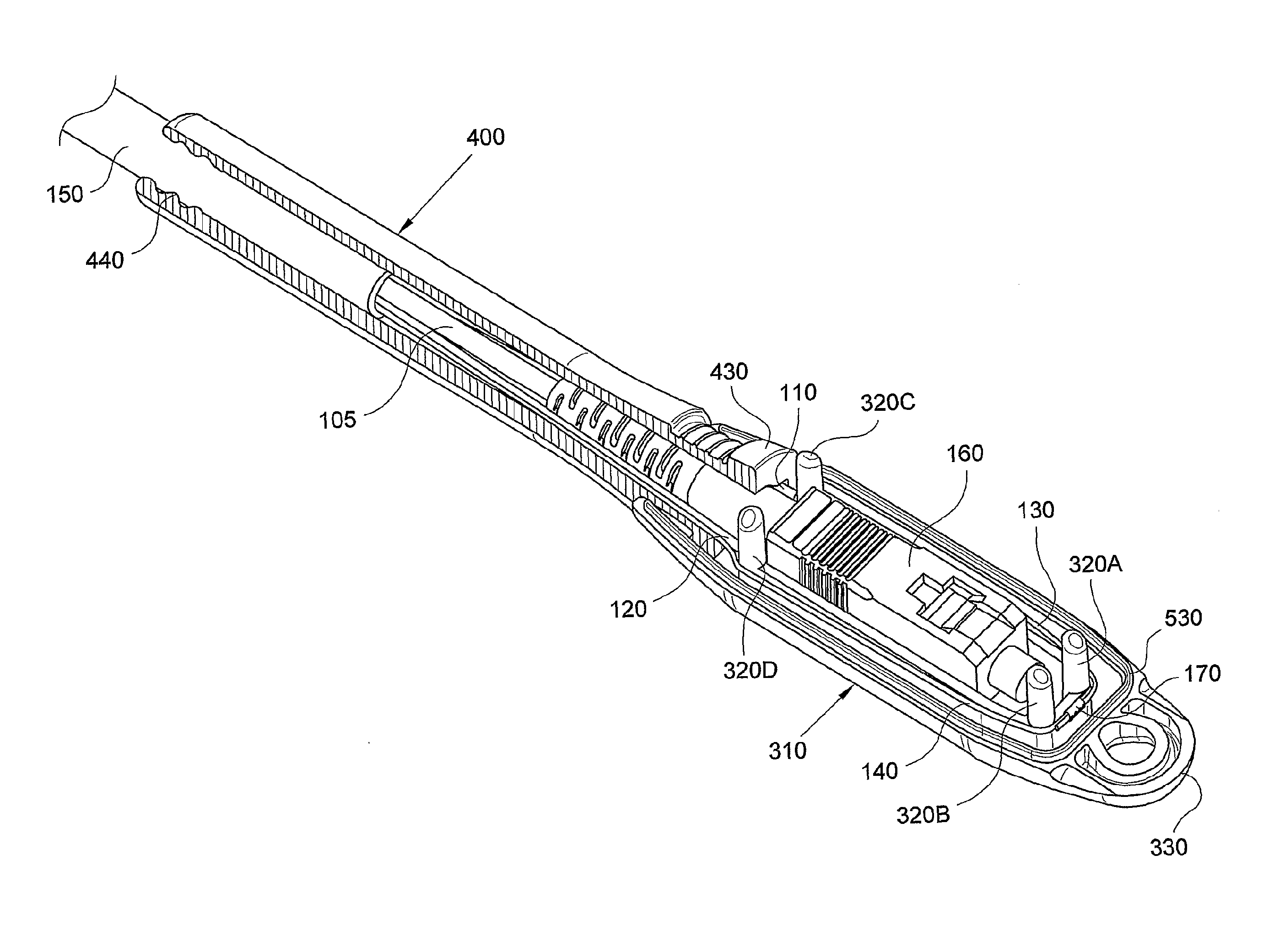
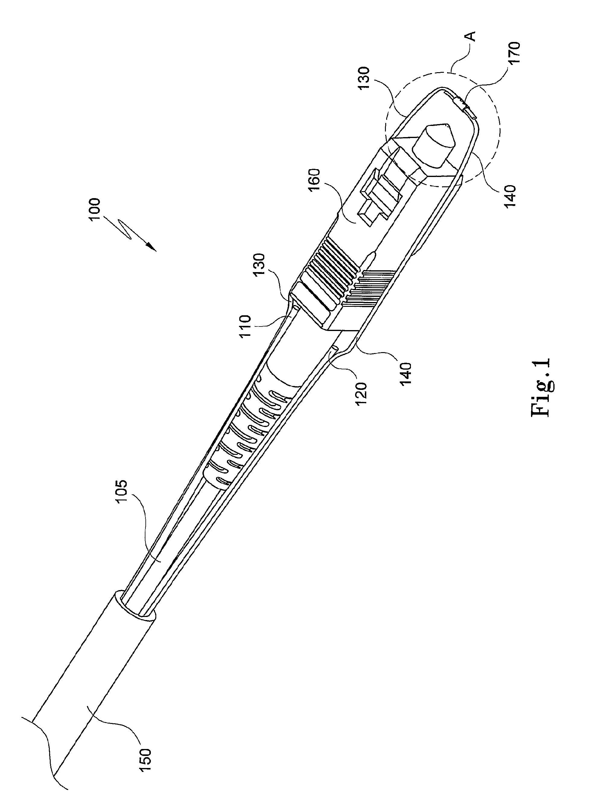
[0095]Referring to FIG. 1, fibre optic cable 100 includes a central jacket 105 which is used for protecting a single optic fibre (not visible in the figures). Typically, the single optic fibre is a single-mode fibre. Alternatively, the optic fibre is a multi-mode fibre. Preferably, a tight acrylate buffered fibre is used; the latter has typically a diameter of, about 245 μm. The central jacket 105 may be made from a, polymeric material, e.g. polyamide, and has a diameter which can be of about 900 μm. Alternatively, reference numeral 105 may refer to the single optic fibre itself in the case a central protective jacket...


PUM


Abstract

A hauling shroud, a cable termination and methods of hauling a fiber optic cable with a pre-connected optic termination along a conduit. The hauling shroud protects the optic termination when being hauled along the conduit. The hauling shroud includes a first housing member and a second housing member such that the first housing member and the second housing member can be joined together to enclose the optic termination. At least one anchoring member is used, for example, connecting pins, such that at least one strengthening element of the fiber optic cable engages with the anchoring member inside an internal cavity formed within the hauling shroud. Alternatively, at least two strengthening elements of the fiber optic cable are attached together to form a loop which engages with the at least one anchoring member, e.g., the connecting pins. This prevents any hauling forces from being applied to the optic termination.

Description

CROSS REFERENCE TO RELATED APPLICATION[0001]This application is a national phase application based on PCT / AU2006 / 001403, filed Sep. 26, 2006, the content of which is incorporated herein by reference.TECHNICAL FIELD[0002]The present invention relates to hauling or pulling a fibre optic cable along a conduit, pipe or the like, and in particular, to a hauling shroud, cable termination and methods for allowing the hauling or pulling of a fibre optic cable along the conduit, pipe or the like, said cable being provided with a pre-connected optic connector.BACKGROUND ART[0003]Traditionally, in a telecommunications network, users' or customers' premises are connected to a Public Switched Telephone Network (PSTN) by a lead-in cable consisting of either one or two pairs of copper conductors (wires). The lead-in cable is routed to a dwelling or other premises either aerially, in the case of an aerial Customer Access Network (CAN), or underground for the more recently deployed underground CANs....

Claims


Application Information

Patent Timeline
Patent Type & Authority Patents(United States)
IPC IPC(8): G02B6/00
CPCG02B6/54H02G1/081G02B6/545
Inventor PIERCE, ANDREW ELIOTMENNIE, ALEXANDERKACZMARSKI, ANDREWBOLTO, KYLE
Owner PRYSMIAN AUSTRALIA
Why Eureka
Try Eureka