
Control system for can coating

a control system and can coating technology, applied in coatings, liquid surface applicators, spraying apparatuses, etc., can solve the problems of not being properly coated, not spinning properly, and not being properly coated

Active Publication Date: 2013-11-12
NORDSON CORP
View PDF21 Cites 14 Cited by
  • Summary
  • Abstract
  • Description
  • Claims
  • Application Information

AI Technical Summary

Benefits of technology

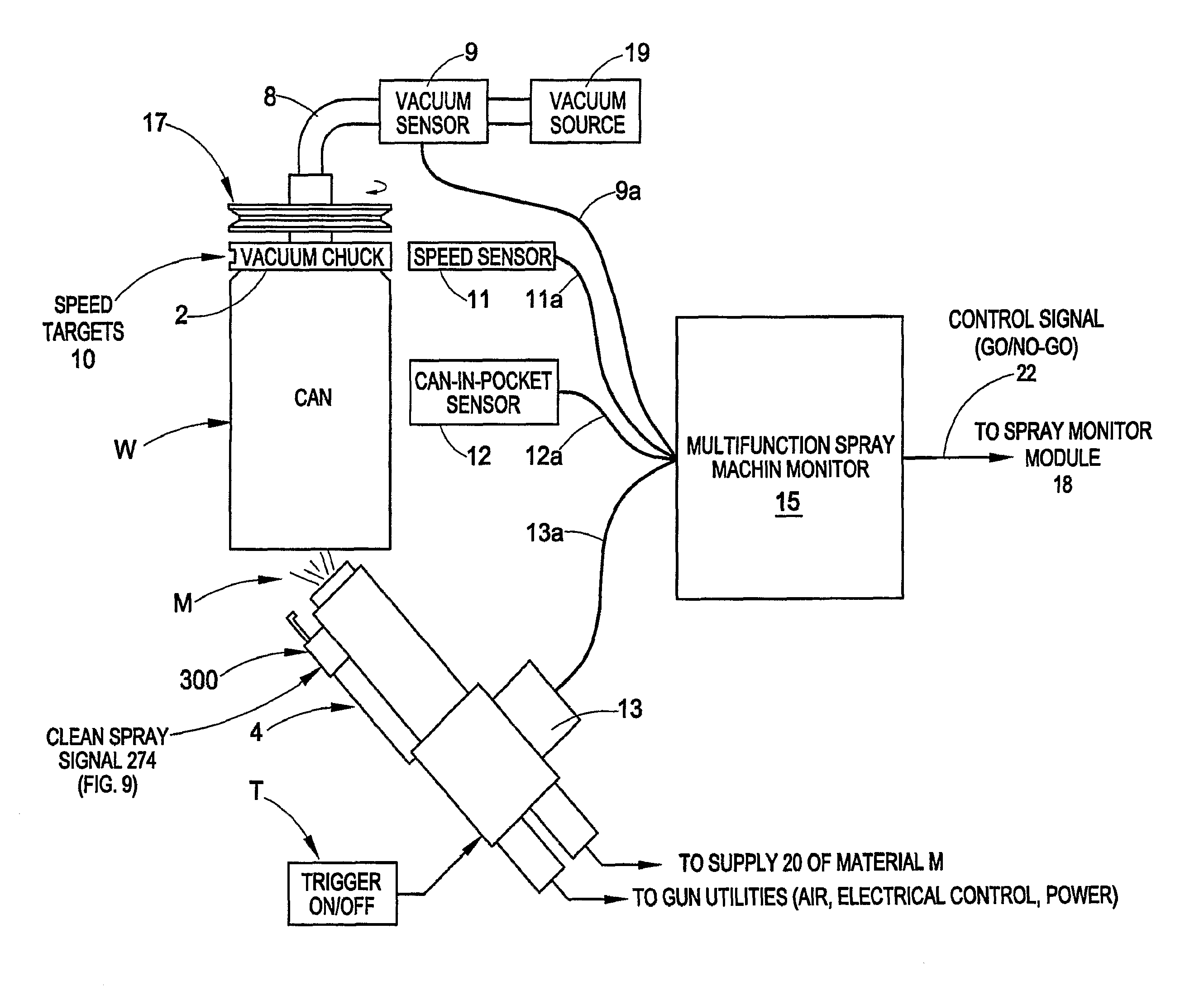
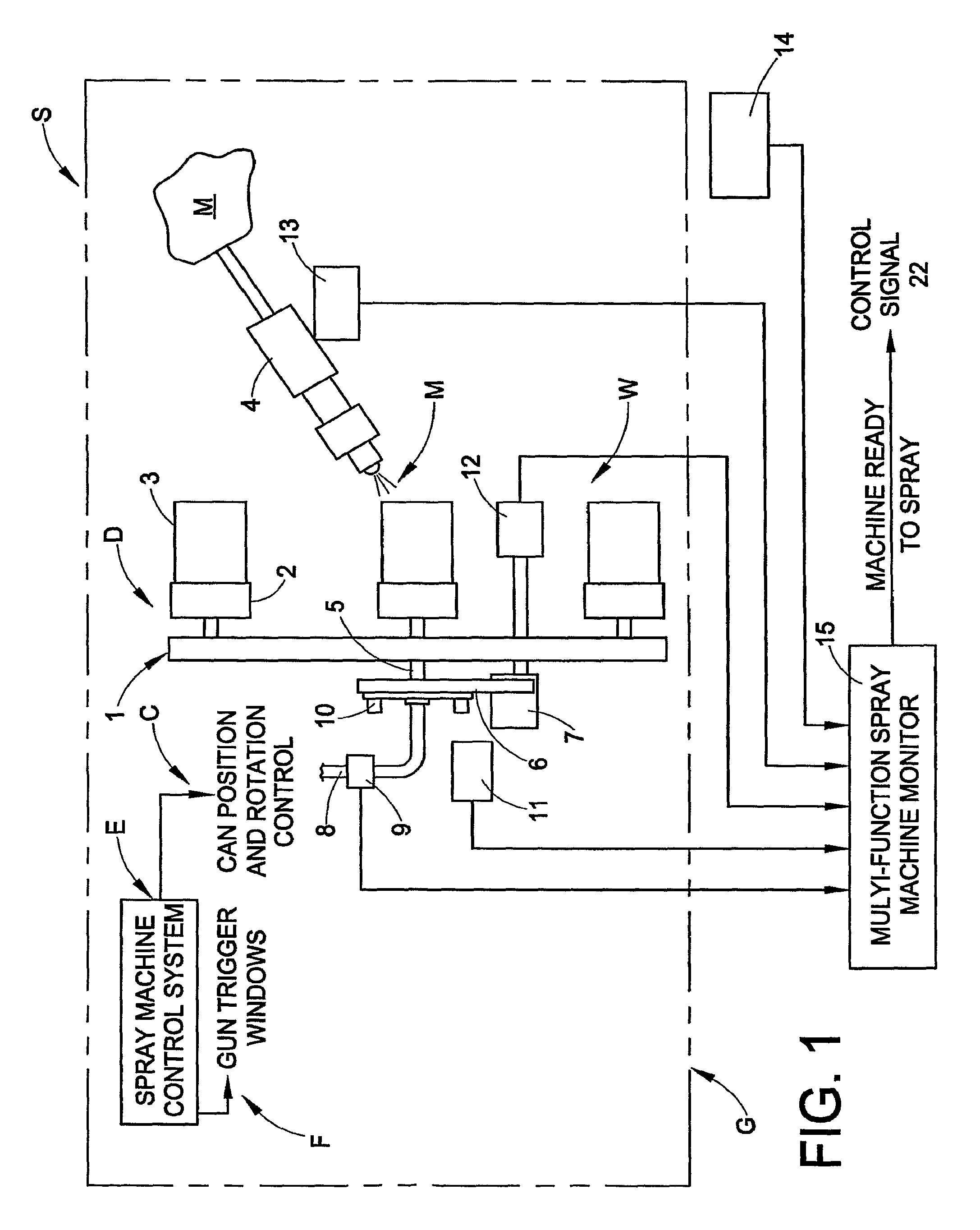
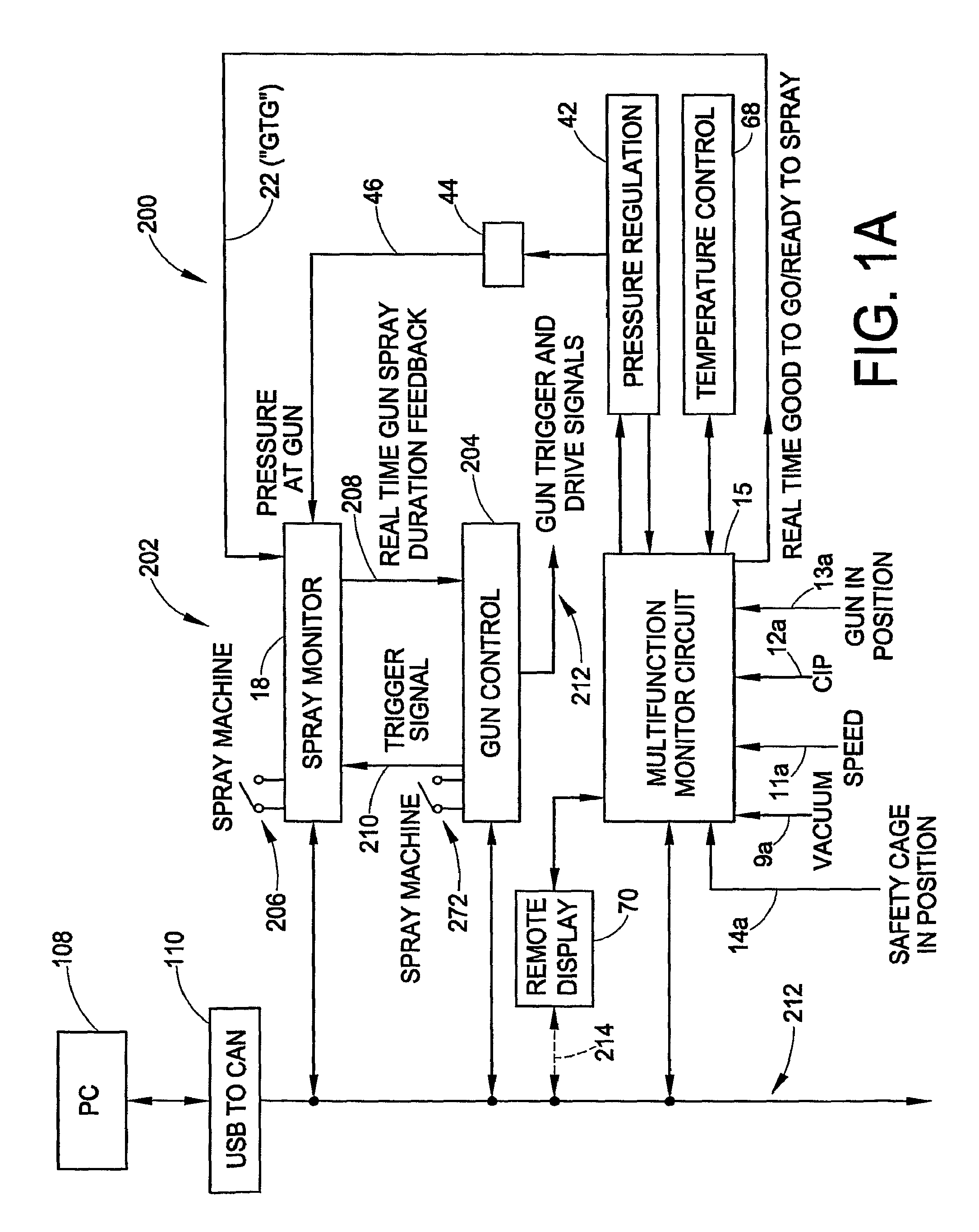
[0016]In accordance with another inventive aspect of the disclosure, a modular control system for a work piece coating system is contemplated. The modular concept utilizes two or more functional modules that may communicate with each other over a network, as well as with an operator interface device such as a computer. Each module includes control and / or monitoring functionality and associated circuits. The modular design allows for selective configuration of a coating system by including modules as needed for specific functions. The networked modular design also allows for simple extension of the system for additional spray guns and spray machines. In an exemplary embodiment, modules may be provided for gun control, pressure control, temperature control, remote displays and multifunction “good-to-go” control signal generation.

Problems solved by technology

However, lower coating weights necessitate tighter control over the coating process.
Even though a can is set to rotate at a desired speed on a spray machine as described above, the can may not be spinning properly.
If the can is not rotated properly during the spraying operation, it may not be properly coated.
It is also possible that even though the can is properly rotated, it is not properly sprayed.
Improperly coated cans must be detected before they are filled with a food or beverage and sold to a consumer.

Method used


Image

  • Control system for can coating
  • Control system for can coating
  • Control system for can coating

Examples


Embodiment Construction

1. Introduction

[0034]The present disclosure is directed to apparatus and methods for application of material onto a work piece surface, such as, for example, the rotating surfaces of a can. In an exemplary embodiment, the inventions are illustrated herein for use with a spray coating process and apparatus for spraying a coating material, such as for example water and / or solvent borne coating material, to the interior surface of a rotating can body. For example, coating material may be applied to the interior surface of a two piece or three piece can body or outside dome spray.

[0035]While the inventions are described and illustrated herein with particular reference to various specific forms and functions of the apparatus and methods thereof, it is to be understood that such illustrations and explanations are intended to be exemplary in nature and should not be construed in a limiting sense. For example, the inventions may be utilized in any material application system involving the a...


PUM


Abstract

A can coating machine control system includes a coating control signal that functions as a go / no-go signal based on a plurality of monitored conditions such as can in position, vacuum pressure, gun in position, guard in position and speed condition. Local pressure regulation of the coating material in the spray gun is provided along with optional control of the material temperature. Local pressure regulation allows for optional spray weight control based on a wrap number derived from speed and gun spray-durations. A CAN to CAN network buffer is provided as well for primary network isolation. A gun control circuit may be used to select specific gun drive signals and to adjust gun drive signals based on real-time feedback of the actual spray duration.

Description

RELATED APPLICATION[0001]This application claims the benefit of U.S. Provisional patent application Ser. No. 60 / 746,790 filed on May 9, 2006 for IMPROVED CONTROL SYSTEM FOR CAN COATING, the entire disclosure of which is fully incorporated herein by reference.TECHNICAL FIELD OF THE DISCLOSURE[0002]The disclosure relates generally to apparatus and methods for spraying or otherwise applying coating material onto a surface, such as, for example, the inferior surfaces of a rotating can. More particularly, the disclosure relates to monitoring and control functions useful for coating operations.BACKGROUND OF THE DISCLOSURE[0003]Spraying a coating material onto the surface of a body is commonly done. For example, interior surfaces of metal beverage cans are coated to preserve the flavor of the contents from being changed due to contact with a metal surface. A variety of spray systems have been developed over the years. In the can industry, can interiors are sprayed using one or more spray a...

Claims


Application Information

Patent Timeline
Patent Type & Authority Patents(United States)
IPC IPC(8): B05C11/10
CPCB05B12/008B05B13/0228B05B13/0242B05B12/087B05D1/02B05B12/02B05B13/0609B05C5/02B05C5/0208
Inventor KHOURY, JAMES M.NAGY, CHARLESNEMETHY, STEPHEN G.IGNATIUS, MARK J.
Owner NORDSON CORP
Learn More