Wire guiding device

a guiding device and wire technology, applied in the direction of cables, lifting equipment, special-purpose vessels, etc., can solve the problems of the need, inability to address the need for two electricians, and previous devices that have attempted to damage the wire, so as to prevent damage to the wire

Active Publication Date: 2013-11-12
RAINERI DENNIS
View PDF31 Cites 6 Cited by
  • Summary
  • Abstract
  • Description
  • Claims
  • Application Information

AI Technical Summary

Benefits of technology

[0010]The present invention meets the above described need by providing a wire guiding device that uses two rollers in combination. A first roller allows a wire to be pulled around the angle of the fitting and may be of sufficient diameter to prevent damage to the wire, while a second roller may prevent the wire from contacting the damaging edges of the fitting. The rollers are mounted within a frame which is adaptable to the access port of an LB fitting. Holes may be located in the frame such that fasteners engage the pre-existing threaded holes located in a standard LB fitting. In this way, the device may be attached to the LB fitting and removed for use elsewhere. The rollers are affixed to the frame by way of removable axles such that the wire, being interlaced through the rollers during use, can be removed from the device after the wire pulling has been completed.

Problems solved by technology

Even if the first electrician could apply enough pulling force to the wire, an unacceptable amount of damage would likely be done to the wire.
Previous devices have attempted to address the difficulties in wire pulling but have not been able to address both the need for two electricians and the need to avoid damage to wire.
However, such devices still require a second electrician to guide the wire through the fitting.
However, these prior art devices suffer from a small size of the roller used.
Wire pulled through such a device may not be damaged by contact with the sharp edges of the fitting, but may still be damaged by the act of being pulled around a roller of insufficient radius.
Such damage is readily apparent when the wire being pulled is an optical fiber cable in which one or more glass fibers within the cable must not be bent around a radius below a certain threshold.

Method used


Image

  • Wire guiding device
  • Wire guiding device
  • Wire guiding device

Examples


Embodiment Construction

[0018]As used herein, the term “wire” is meant to encompass wire, cable, string, and other materials (electrical, optical, or otherwise) which may be installed into conduit.

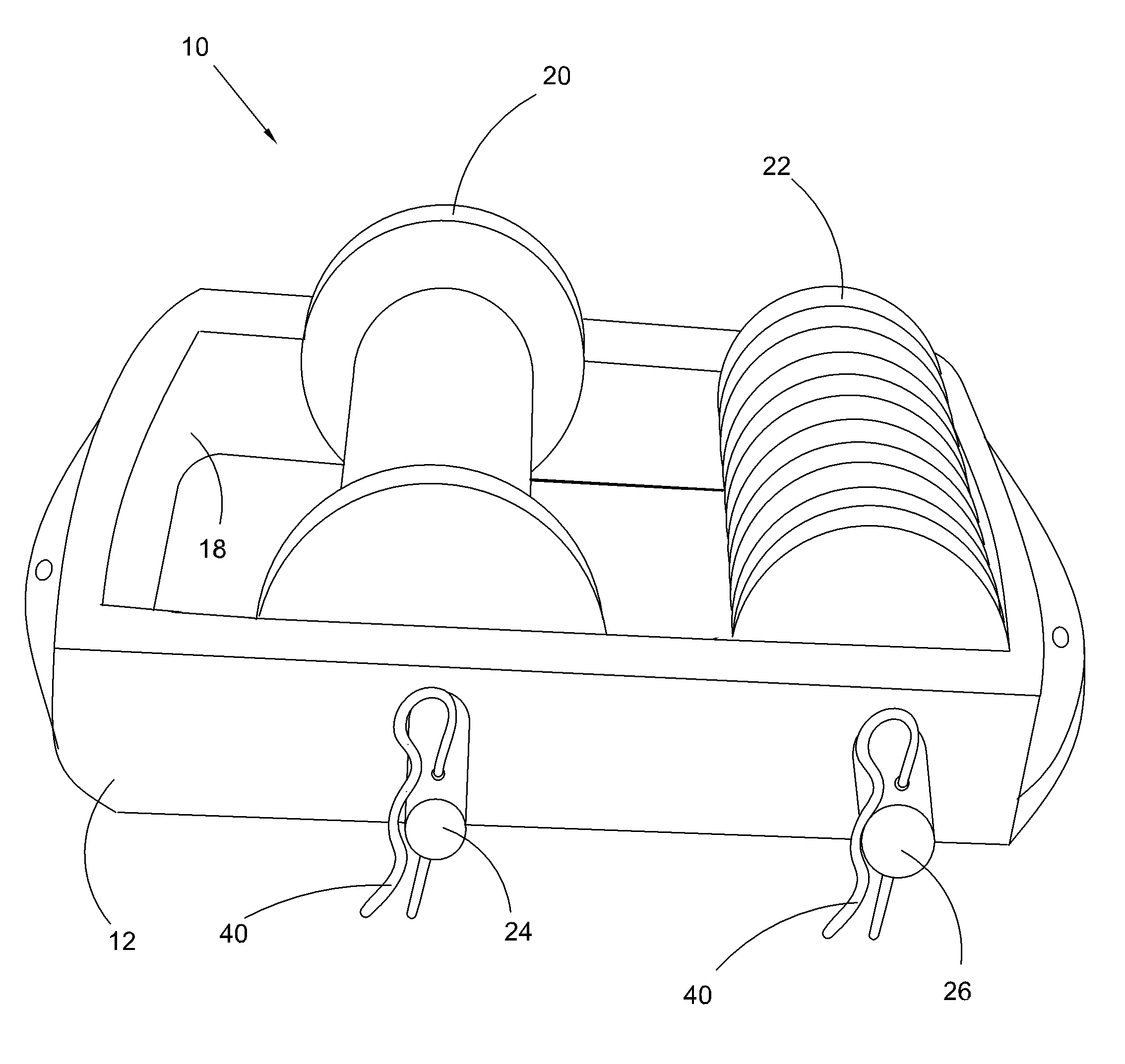
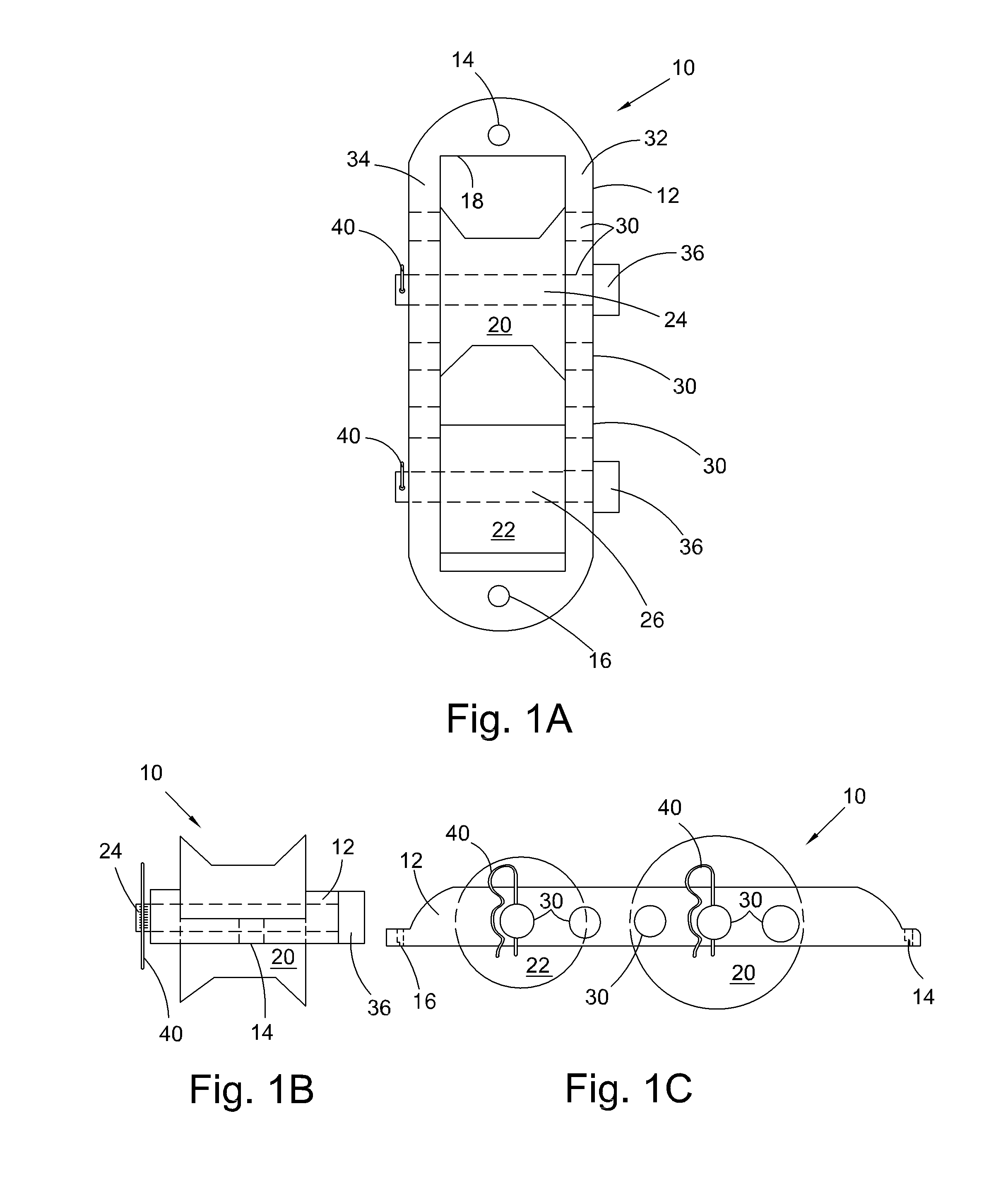
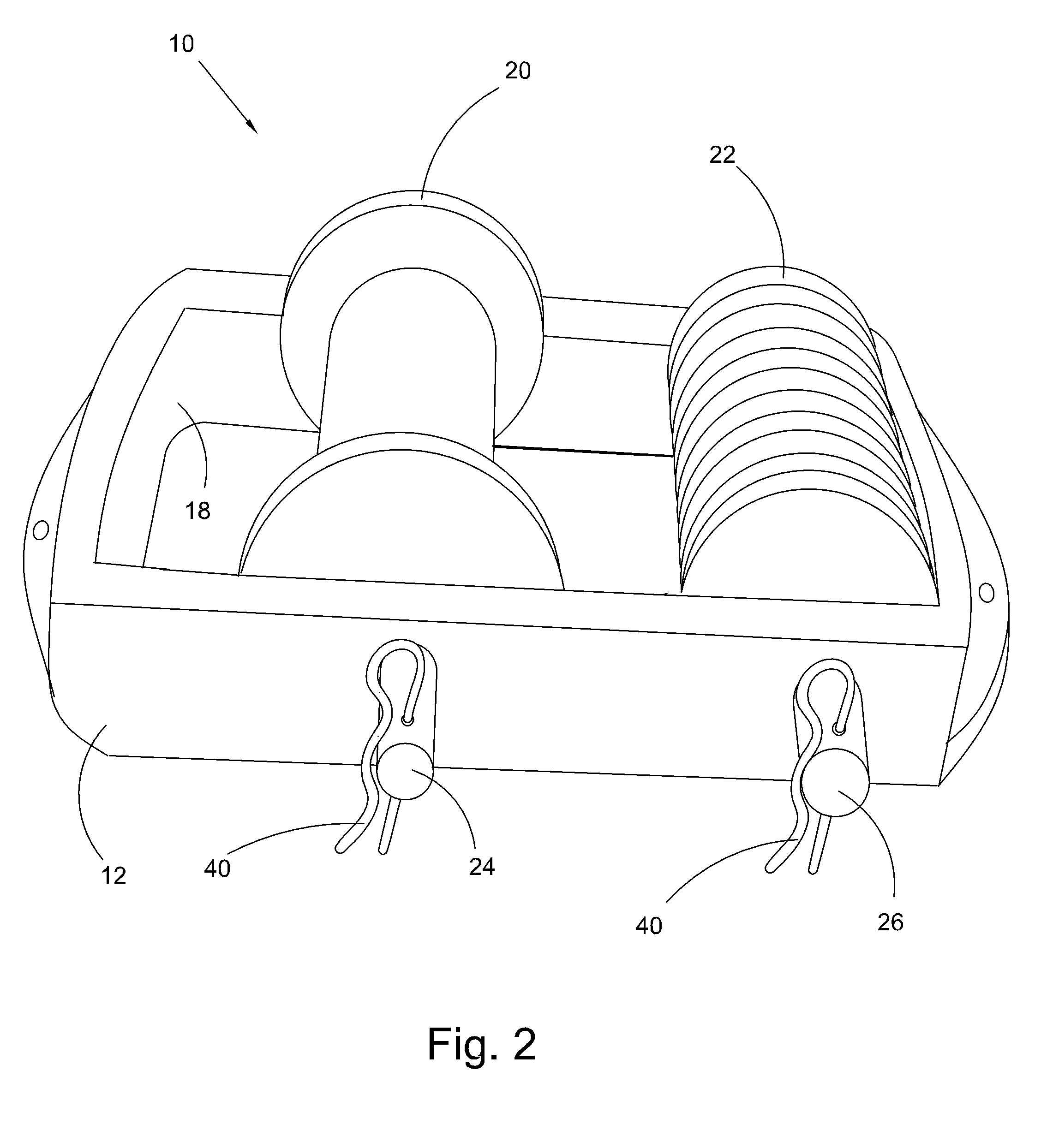
[0019]In FIGS. 1a-1c and 2, a device 10 according to an embodiment of the present invention is shown, wherein a frame 12 is adaptable to be attached to the access orifice of an LB fitting. The frame 12 may be made from metal or plastic. The frame 12 may contain two holes 14, 16, for attachment to the LB fitting using fasteners typically provided with such a fitting (fasteners are typically provided with each LB fitting in order to secure a cover over the access orifice). The frame 12 may be adapted for attachment to the LB fitting external to the fitting, within the fitting, or a combination of both.

[0020]The frame 12 contains a pass-through orifice 18 wherein a first roller 20 is mounted on a first axle 24 and a second roller 22 is mounted on a second axle 26. At least two holes 30, suitable for pass-through of ...


PUM


Abstract

A wire guiding device for use with an electrical fitting such as an “LB” fitting is provided. The wire pulling device comprises a frame and two rollers mounted on axles. A first roller allows a wire to be pulled around the angle of the fitting and may be of sufficient diameter to prevent damage to the wire, while a second roller may prevent the wire from contacting the damaging edges of the fitting. The rollers are mounted within a frame which is adaptable to the access port of an LB fitting. Holes may be located in the frame such that fasteners engage the pre-existing threaded holes located in a standard LB fitting.

Description

CROSS-REFERENCE TO RELATED APPLICATION[0001]This application claims the benefit of priority to U.S. provisional patent application Ser. No. 61 / 102,810, filed on Oct. 3, 2008, now pending, which application is hereby incorporated by reference.FIELD OF THE INVENTION[0002]The present invention relates to a guiding attachment for an angle fitting, such as an LB fitting, for use in pulling cable through conduit.BACKGROUND OF THE INVENTION[0003]Rigid conduit, made from metal or plastic, is commonly employed by electricians in commercial, industrial, and, occasionally, residential structures. Such conduit may be selected by the electrician for easy of use, flexibility in future expansion, or such conduit may be required by electrical codes.[0004]The construction of rigid conduit has been standardized to enable components from different manufacturers to be utilized together and also so that standardized tools may be used in assembly and construction. Conduit includes pipes and fittings, as ...

Claims


Application Information

Patent Timeline
Patent Type & Authority Patents(United States)
IPC IPC(8): B66D3/04
CPCH02G1/08H02G3/08
Inventor RAINERI, DENNIS
Owner RAINERI DENNIS
Why Eureka
Try Eureka