Switch device

a technology of switch and contact, which is applied in the direction of dc motor stoppers, door/window fittings, wing accessories, etc., can solve the problems of affecting the operation of the switch unit as a whole, damage to the contacts, and the 14v system being hardly capable of providing sufficient power, so as to prevent the damage of the contacts and reduce the time lag in switching between contacts.

Inactive Publication Date: 2005-11-29
ORMON CORP
View PDF17 Cites 1 Cited by
  • Summary
  • Abstract
  • Description
  • Claims
  • Application Information

AI Technical Summary

Benefits of technology

[0026]It is therefore an object of this invention to provide a switch device which will not cause the switch unit to become large when applied to a 42V electrical system, while being able to prevent damages to the contacts and causing no increase in the time lag in switching between contacts.
[0029]If the closed one of the two NO contacts of the first switch element is returned to its normally open condition while the DC motor is rotating as explained above, the DC motor stops its rotation. In this situation, during the period from the starting moment when the closed NO contact of the first switch element begins to be opened until the corresponding NC contact completes its change from the open condition to the closed position, the corresponding NC contact of the second switch element is maintained in the open condition such that the current route between the NC contacts of the first switch element and the lower voltage source line and hence no large instantaneous current can be generated and damage to the contacts of the first switch element can be prevented.
[0032]If the closed one of the two NO contacts of the first switch element is returned to its normally open condition while the DC motor is rotating as explained above, the DC motor stops its rotation. In this situation, before the closed one of the NO contacts of the first switch element changes from a closed condition to an open condition, the corresponding NC contact of the second switch element is allowed (say, by a manual operation) to be in an open condition such that the current route between the NO contacts of the first switch element and the higher voltage source line and hence no large instantaneous current can be generated and damage to the contacts of the first switch element can be prevented.
[0035]If the closed one of the two NO contacts of the first switch element is returned to its normally open condition while the DC motor is rotating as explained above and the corresponding NC contact of the second switch element is returned to its closed condition, the DC motor stops its rotation. In this situation, before the closed one of the NO contacts of the first switch element changes from a closed condition to an open condition, the corresponding NC contact of the second switch element is allowed to be returned to the closed condition such that the NO contacts of the first switch element can support a sufficiently large voltage for an arc discharge and the generation of a large instantaneous current can be prevented although the NC contact connected to this NO contact of the first switch element becomes closed and hence damage to the contacts of the first switch element can be prevented.

Problems solved by technology

Since an increased number of electronic devices are being carried on automobiles, however, a 14V system is sometimes hardly capable of supplying sufficient power.
If such a prior art switch system is used with a 42V electrical system, however, an overly strong current will flow between a specified pair of contacts at the return time from the UP condition to the neutral condition or from the DOWN condition to the neutral condition, thereby damaging these contacts.
If the gap is thus increased, however, the switch unit as a whole becomes large and may be inconvenient for being used on a vehicle.

Method used


Image

  • Switch device
  • Switch device
  • Switch device

Examples


Embodiment Construction

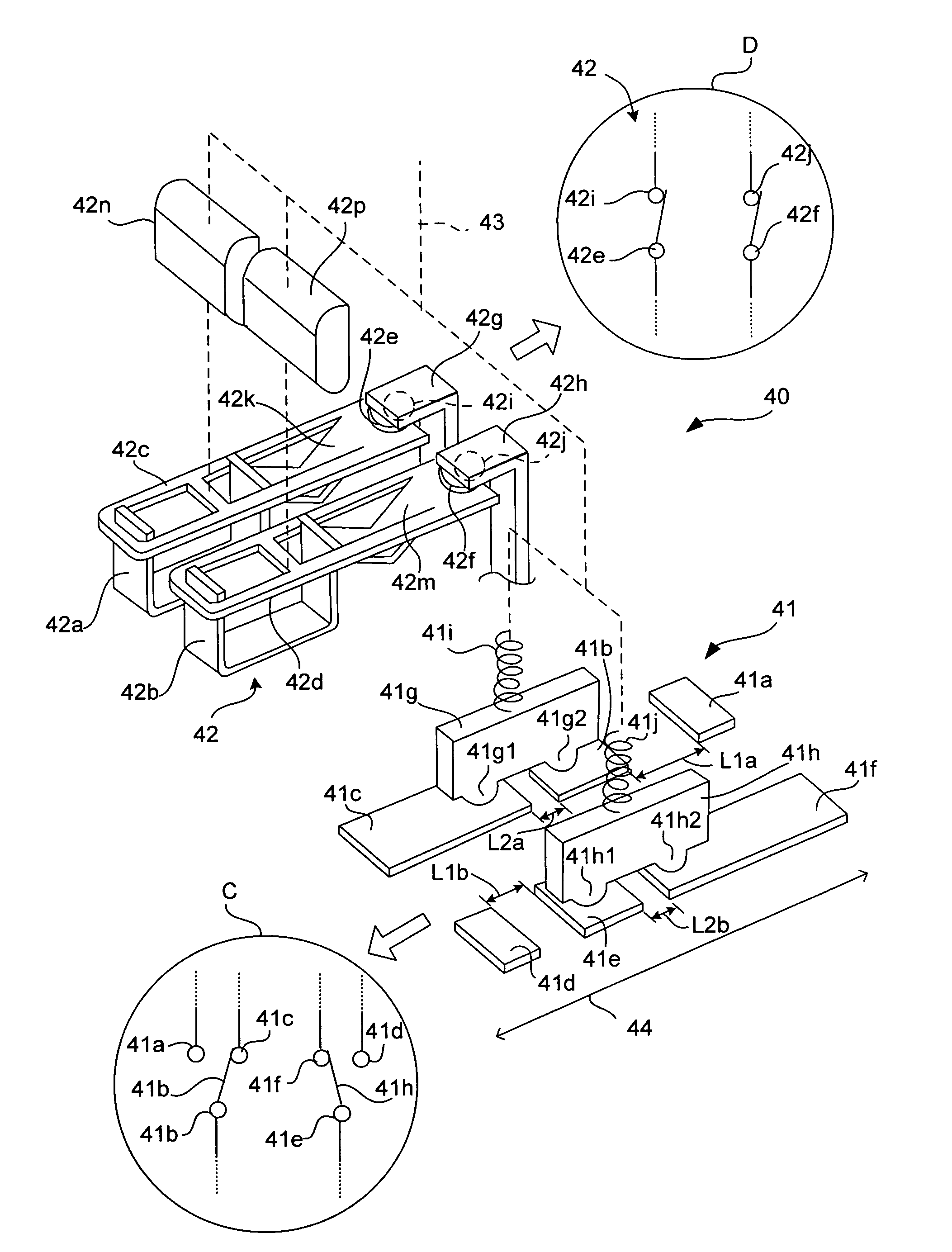
[0049]The invention is described next by way of examples. FIG. 1 shows a switch device 40 according to a first embodiment of this invention, which may be roughly characterized as comprising two switch elements (the first switch element 41 and the second switch element 42) and an operating element 43 for carrying out the switching operations of these two switch elements 41 and 42.

[0050]Next, each of these elements will be described individually. The first switch element 41 is comprised of six fixed electrodes 41a–41f each made of a planar metallic conductor inserted inside a molded base (not shown) or formed as a thin film and two mobile members 41g and 41h. The metallic material for these six fixed electrodes has a high electrical conductivity and is strong against wears such as copper, bronze and alloys of copper and iron. These six fixed electrodes are arranged in two group of three each, the first group consisting of electrodes 41a, 41b and 41c and the second group consisting of ...


PUM


Abstract

A switch device for rotating and stopping a DC motor includes a first switch element having two moving contacts, two normally open NO contacts and two normally closed NC contacts, a second switch element having one or two normally closed NC contacts, and an operating element. The operating element serves to connect the two moving contacts individually to input terminals of the DC motor, the two NO contacts to a voltage source line at a higher voltage, and each of the two NC contacts of the first switch element to another voltage source line at a lower voltage such as the ground potential, each through the NC contact, or one of the two NC contacts, of the second switch element. The NC contact of the second switch element is maintained in an open condition during a period from when either one of the NO contacts begins to change from a closed condition to an open condition until the corresponding NC contact of the first switch element finishes changing from an open condition to a closed condition.

Description

BACKGROUND OF THE INVENTION[0001]This invention relates to a switch device for starting and stopping the rotation of a DC electric motor for opening and closing a window of a motor vehicle such as an automobile or for a similar purpose and more particularly to such a switch device for a DC electric motor operating at a high source voltage (such as 42V).[0002]Automobiles currently make use of a 14V electrical system with source voltage of 12V. Since an increased number of electronic devices are being carried on automobiles, however, a 14V system is sometimes hardly capable of supplying sufficient power. As a result of global discussions in consortia representing both universities and industries in view of this problem, a consensus has been obtained from the point of view of safety to human bodies to adopt a voltage system that is three times higher, or a 42V system with source voltage of 36V. Examples of electrical equipment to be operated in a 42V electrical system include DC motors...

Claims


Application Information

Patent Timeline
Patent Type & Authority Patents(United States)
IPC IPC(8): E05F15/16H01H1/12H01H1/40H01H9/38H01H9/54H02P3/10
CPCH01H9/38E05F15/00E05Y2900/55H01H1/403E05F15/689H01H2021/225H01H2300/01E05Y2400/854
Inventor SHIMIZU, KEIICHITANAKA, YASUHIDE
Owner ORMON CORP
Why Eureka
Try Eureka