
Method for providing near-hermetically coated integrated circuit assemblies

a technology of integrated circuit assemblies and coatings, which is applied in the direction of printed circuit liquid treatment, radiation controlled devices, printed electric components, etc., can solve the problems of long life, high cost of production, and relatively short lifespan of cots devices, and achieve the effect of promoting reliability of integrated circuit assemblies

Active Publication Date: 2013-11-12
ROCKWELL COLLINS INC
View PDF145 Cites 6 Cited by
  • Summary
  • Abstract
  • Description
  • Claims
  • Application Information

AI Technical Summary

Benefits of technology

The patent is about a type of integrated circuit that can be mounted on a circuit board. The circuit and the area where it is connected to the board are coated with a special glass-based coating that makes it more reliable in high-temperature and corrosive environments. This helps to make sure that the circuit works properly even in harsh conditions.

Problems solved by technology

These integrated circuit packages (ex—hermetic packages) are often expected to have a long lifespan (i.e., remain functionally operable over a long period of time), such as for 20 years or more, and are typically very costly to produce.
These COTS devices tend to have a relatively short lifespan (ex—2 to 5 years) and are relatively inexpensive to produce compared to military electronics components.
However, when the currently available COTS devices have been subjected to these more rigorous conditions, they have been especially prone to failure due to higher operating temperatures, corrosion, or the like.
Current methods of modifying or designing integrated circuit packages for improved corrosion resistance are typically very expensive and may exacerbate other failure mechanisms and thereby reduce reliability.

Method used


Image

  • Method for providing near-hermetically coated integrated circuit assemblies
  • Method for providing near-hermetically coated integrated circuit assemblies
  • Method for providing near-hermetically coated integrated circuit assemblies

Examples


Embodiment Construction

[0017]Reference will now be made in detail to the presently preferred embodiments of the invention, examples of which are illustrated in the accompanying drawings.

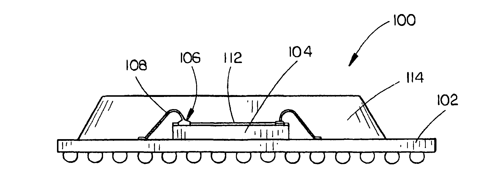
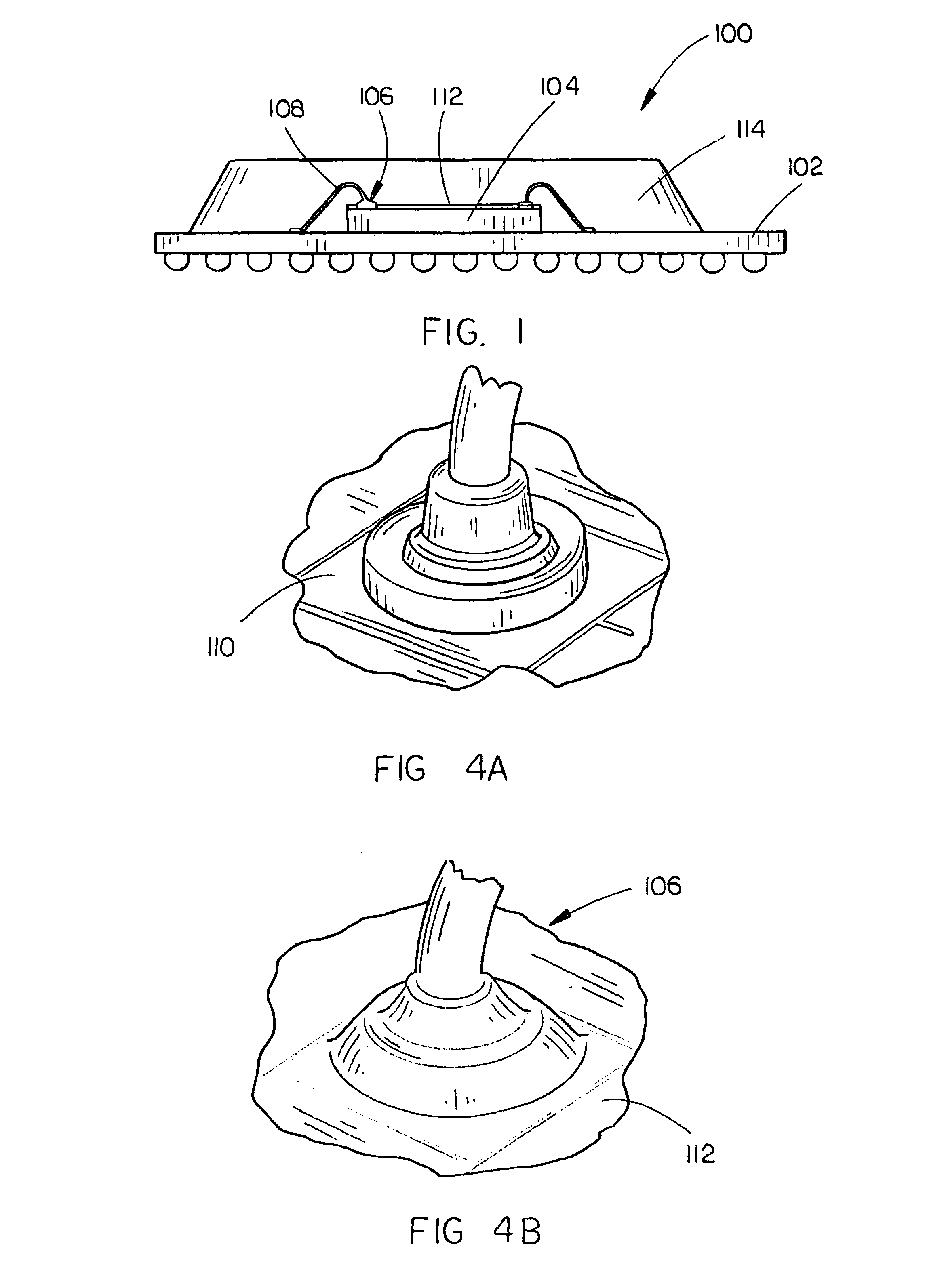
[0018]FIG. 1 illustrates a view of an integrated circuit assembly in accordance with an exemplary embodiment of the present invention. In a present embodiment, the integrated circuit assembly 100 includes a substrate 102. For example, the substrate 102 may be (or may be part of) a chip carrier, such as a Ball Grid Array, a Chip Scale Package substrate, a package substrate, a device substrate, a Ceramic Pin Grid Array (CPGA), a Dual in-line package, an Organic Pin Grid Array (OPGA), a Flip-chip Pin Grid Array, a Pin Grid Array, a Multi-chip Module (MCM), or the like, and may be configured for at least partially encapsulating and protecting an integrated circuit 104. For example, the substrate 102 may form a recessed area which is at least partially guarded by an at least partial enclosure 114 configured for at least partial...


PUM

PropertyMeasurementUnit
Temperatureaaaaaaaaaa

Abstract

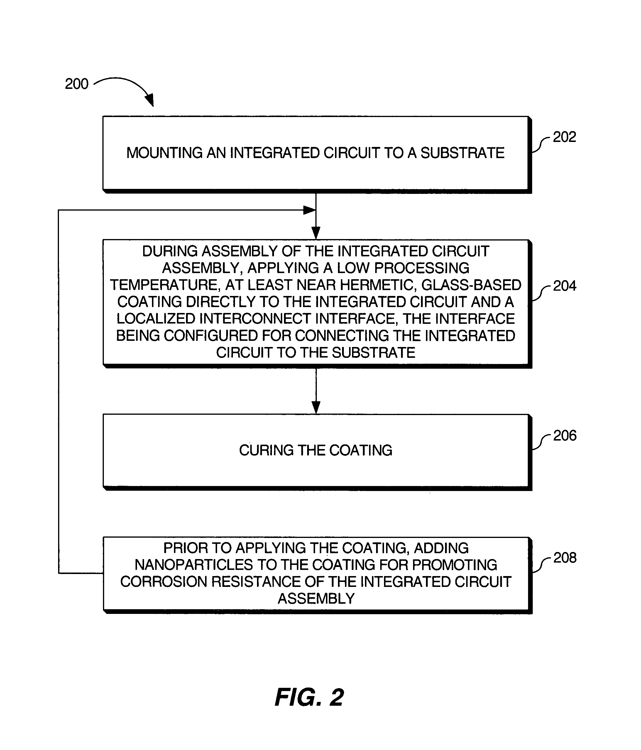
The present invention is a method for providing an integrated circuit assembly, the integrated circuit assembly including an integrated circuit and a substrate. The method includes mounting the integrated circuit to the substrate. The method further includes, during assembly of the integrated circuit assembly, applying a low processing temperature, at least near-hermetic, glass-based coating directly to the integrated circuit and a localized interconnect interface, the interface being configured for connecting the integrated circuit to at least one of the substrate and a second integrated circuit of the assembly. The method further includes curing the coating. Further, the integrated circuit may be a device which is available for at least one of sale, lease and license to a general public, such as a Commercial off the Shelf (COTS) device. Still further, the coating may promote corrosion resistance and reliability of the integrated circuit assembly.

Description

CROSS-REFERENCE TO RELATED APPLICATIONS[0001]The present application is a continuation-in-part application and claims priority under 35 U.S.C. §120 to the U.S. patent application Ser. No. 11 / 508,782 entitled: Integrated Circuit Protection and Ruggedization Coatings and Methods filed Aug. 23, 2006 now U.S. Pat. No. 8,076,185, which is herein incorporated by reference in its entirety.FIELD OF THE INVENTION[0002]The present invention relates to the field of packaging and interconnection of integrated circuit assemblies and particularly to a method for providing near-hermetically coated integrated circuit assemblies.BACKGROUND OF THE INVENTION[0003]Integrated circuit packages are produced for usage in a variety of products or for a variety of applications. For example, integrated circuit packages which are designed for use in military and avionics applications are often required to survive and / or operate under aggressive or rigorous operating conditions and environments. These integrate...

Claims


Application Information

Patent Timeline
IPC IPC(8): H05K1/16
CPCH01L24/29H01L23/24H01L23/291H01L23/3731H01L24/48H01L24/85H05K3/0085H01L2224/29288H01L23/3171H01L24/32H01L24/45H01L24/73H01L2224/04042H01L2224/16225H01L2224/29387H01L2224/32145H01L2224/32225H01L2224/45124H01L2224/45144H01L2224/45147H01L2224/48463H01L2224/4847H01L2224/73265H01L2224/85205H01L2924/10253H01L2924/15787H01L2924/1579H01L2224/85203H01L2224/85206H01L23/3128H01L24/16H01L25/0657H01L2224/13099H01L2224/48227H01L2224/8592H01L2924/01004H01L2924/01006H01L2924/01013H01L2924/01014H01L2924/0102H01L2924/01024H01L2924/01029H01L2924/0103H01L2924/01068H01L2924/01074H01L2924/01082H01L2924/09701H01L2924/14H01L2924/15311H01L2224/48465H01L2224/0401H01L2924/00012H01L2924/00014H01L2924/00H01L2924/181Y10T29/4913Y10T29/49144Y10T29/49155H01L2224/05554H01L2224/85399H01L2224/05599
Inventor BOONE, ALAN P.LOWER, NATHAN P.WILCOXON, ROSS K.
Owner ROCKWELL COLLINS INC
Learn More